Eclipse RatioMatic v3.00 - Design Guide No. 110, 04/98
The flame monitoring control system consists of two main
components:
• Flame Sensor
• Flame Monitoring Control
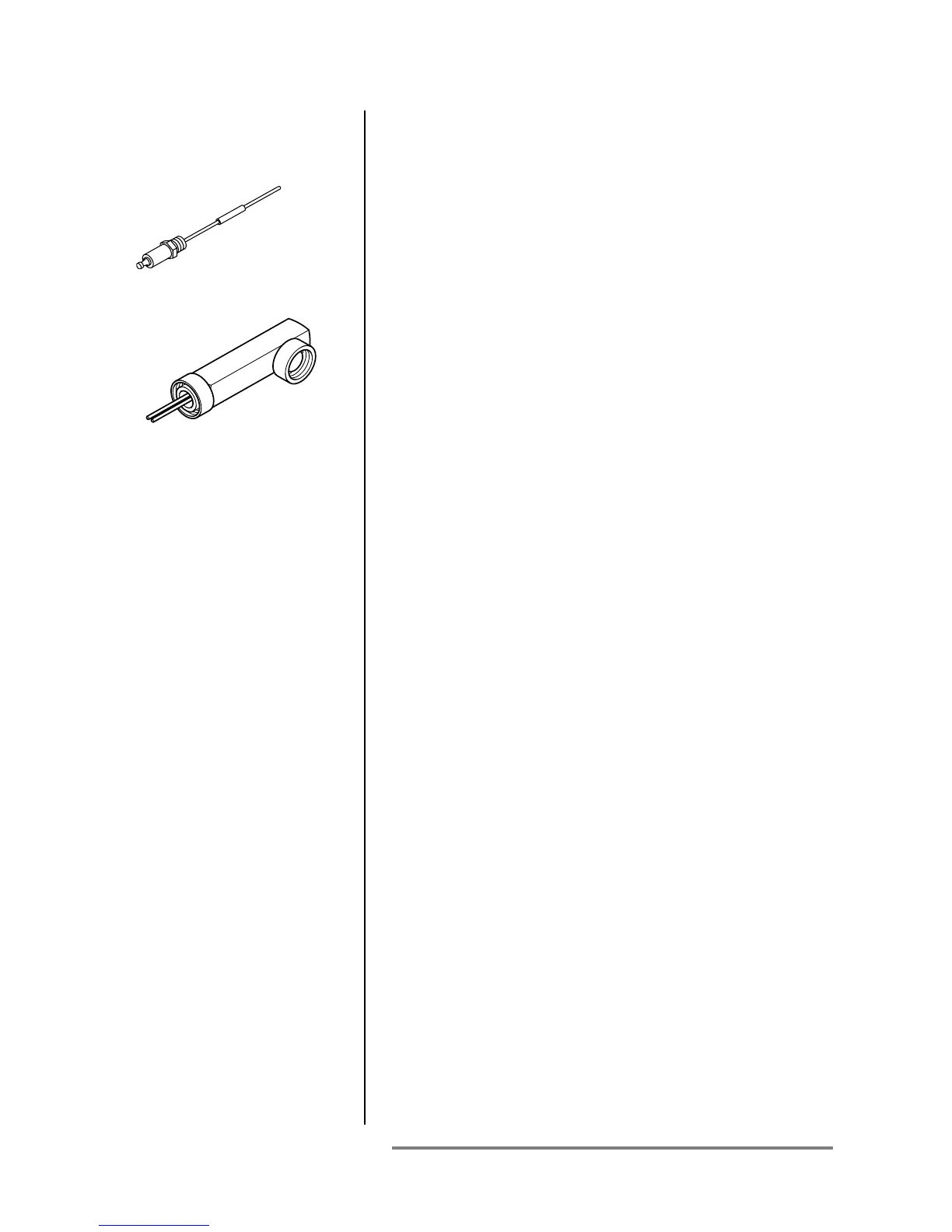
Flame Sensor
Two types can be used on a RatioMatic Burner:
• flame rod
• U.V. scanner
Flame rods are available for all RatioMatic Burner sizes. Further
information can be found in:
• Info Guide 832
A U.V. scanner can be used on all RatioMatic Burner sizes.
Further information can be found in:
• Info Guide 852; 90° U.V. scanner
• Info Guide 854; straight U.V. scanner
• Info Guide 856; self-check U.V. scanner
Flame Monitoring Control
The Flame Monitoring Control processes the signal from the
flame rod, or U.V. scanner, and controls the start-up sequence
and the main gas shut-off valve sequence.
Eclipse Combustion recommends the use of flame monitoring
control systems which maintain a spark for the entire trial for
ignition time when using U.V. scanners. Some of these flame
monitoring models are:
• Veri-Flame; see Bulletin / Info Guide 610, 620, 630
• Bi-Flame series; see Instruction Manual 826
• Multi-Flame series 6000; see Instruction Manual 820
DO NOT USE:
• PCI Automatic flame monitoring
• Honeywell RM7890 series flame monitoring
• Flame monitoring relays which interrupt the trial for ignition
when the flame is detected.
• Flame sensors which supply a weak signal.
• Flame monitoring relays with low sensitivity.
3-8
Flame Rod
U.V. Scanner
Step 5: Flame Monitoring
Control System