12
57-600 Eclipse
®
Guided Wave Radar Transmitter
2
.4.2.2 To install a Model 7x7 standard flexible twin rod probe:
➀ Make sure the process connection is at least 2" NPT or a
flanged mounting.
➁ Make sure that there is at least 1" (25 mm) spacing between
the active probe rod and any part of the tank (walls, still-
well, pipes, support beams, mixer blades, etc.). Minimum
stillwell diameter for Twin Rod probe is 3".
➂ Carefully place the probe into the vessel. Align the gasket
on flanged installations.
➃ Align the probe process connection with the threaded or
flanged mounting on the vessel.
➄ For threaded connections, tighten the hex nut of the probe
process connection. For flanged connections, tighten flange
bolts.
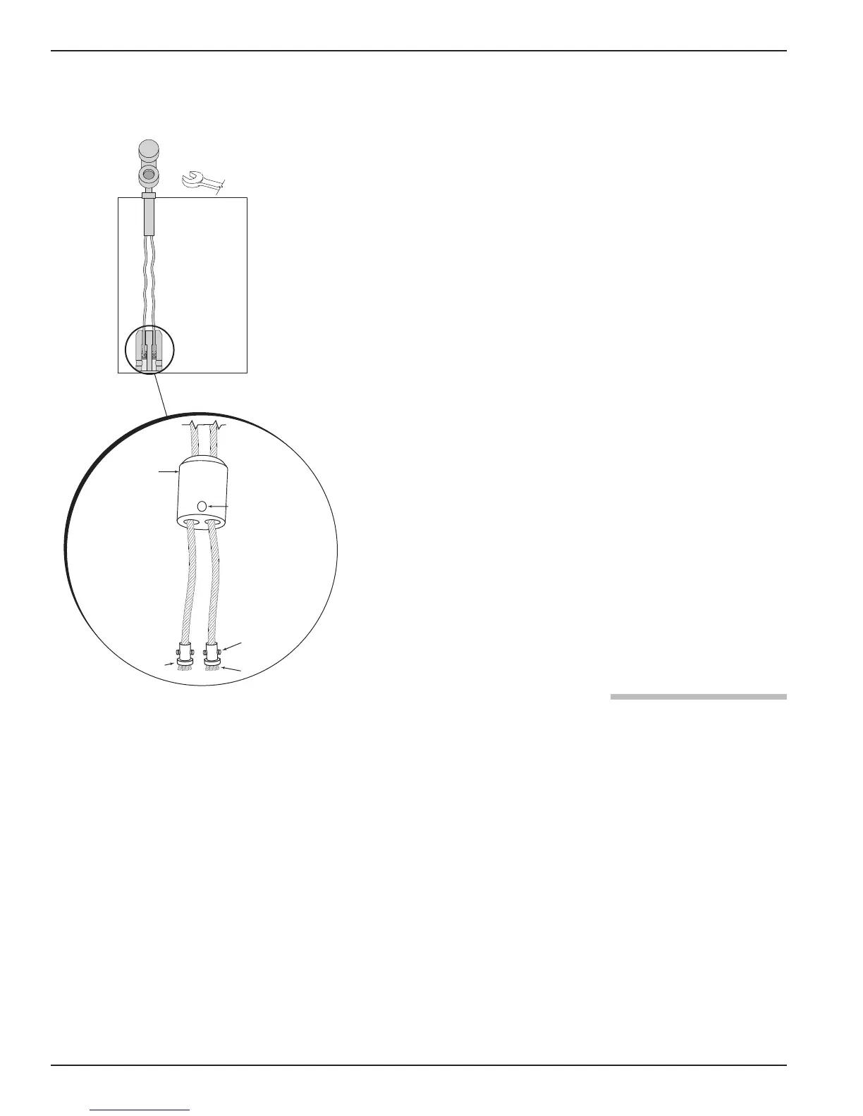
Probe can be shortened in the field:
➅ a. Raise the weight (1) to expose the two securing devices (2).
b. Loosen the two #10-32 set screws (3) on both securing
devices using a
3
⁄3
2
" (2.5 mm) hex wrench and slide the
securing devices off of the probe.
c. Slide the TFE weight off of the probe.
d. Cut and remove the required cable (4) length.
e. Remove 3
1
⁄2" of the rib between the two cables.
f. Strip
5
⁄8" (16 mm) of coating from the two cables.
g. Slide the TFE weight back on to the probe.
h. Reattach securing device and tighten screws.
i. Enter new probe length (inches or cm) in software.
2.4.3 Installing a Single Rod Probe
(Models 7x1, 7x2, 7xF, 7xJ)
Before installing, make sure the:
• Model and serial numbers on the nameplates of the
ECLIPSE probe and transmitter are identical.
• Probe has adequate headroom for installation and has unob-
structed entry to the bottom of the vessel.
• Process temperature, pressure, dielectric, viscosity, and
media buildup are within the probe specifications for the
installation. See Specifications, Section 3.6.
• Nozzle does not restrict performance by ensuring the
following:
1. No nozzle is <2" (50mm) diameter.
0.50" (13 mm) Ø
1
3
2
4
➀
➁
➅
➅
➂
➃➄