1.1.2 Configuration Information
Some key information is needed to configure the
ECLIPSE transmitter. Complete the following operating
parameters table before beginning configuration.
D
isplay Question Answer
P
robe Model What probe model is listed on the
model information?
(first four digits of probe model number) _____________
Probe Mount Is the probe mounted NPT, BSP,
or flange? _____________
Measurement What is the desired measurement? Choices
Type are: Level only, volume, interface level
or interface level and volume. _____________
Level Units What units of measurement will be
used? (inches, centimeters, feet or meters)
(AI block parameter. Not selectable at
t
ransmitter on Model 705 Fieldbus)
_____________
Probe Length What probe length is listed on the
model information? _____________
Level Offset The desired level reading when the
liquid is at the end of the probe. _____________
Dielectric What is the dielectric constant range
of the process medium? (Upper layer
dielectric for interface applications) _____________
Loop Control Is the output current to be controlled
by level or volume? _____________
Set 4.0 mA What is the 0% reference point for the
4.0 mA value? (EU_0 value for
F
OUNDATION fieldbus) _____________
Set 20.0 mA What is the 100% reference point for
the 20.0 mA value? (EU_100 value for
F
OUNDATION fieldbus) _____________
(Top 6" (152 mm) of Single Rod probes is within
Blocking Distance)
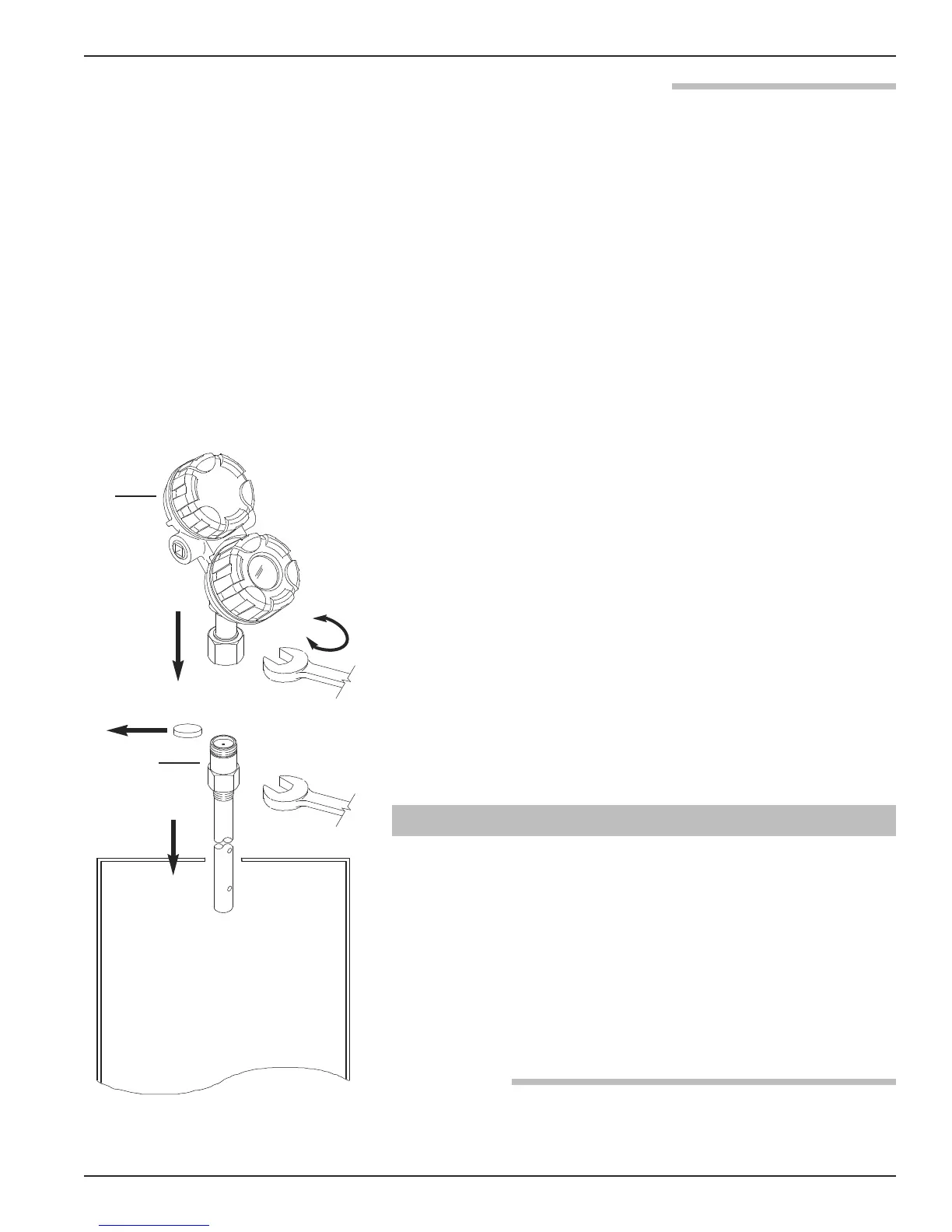
1.2 QuickStart Mounting
NOTE: Confirm the configuration style and process connection
size/type of the ECLIPSE transmitter. Ensure it matches the
requirements of the installation before continuing with the
QuickStart installation.
① Confirm the model and serial numbers on the nameplates
of the ECLIPSE probe and transmitter are identical.
NOTE: For applications using the Model 7xQ or 7xS steam probes, it
is mandatory to keep the transmitter and probe matched as a
set.
1.2.1 Probe
② Carefully place the probe into the vessel. Align the probe
process connection with the threaded or flanged mounting
on the vessel.
①
④
⑥
⑤
⑦
②
③
①
5
57-600 Eclipse
®
Guided Wave Radar Transmitter