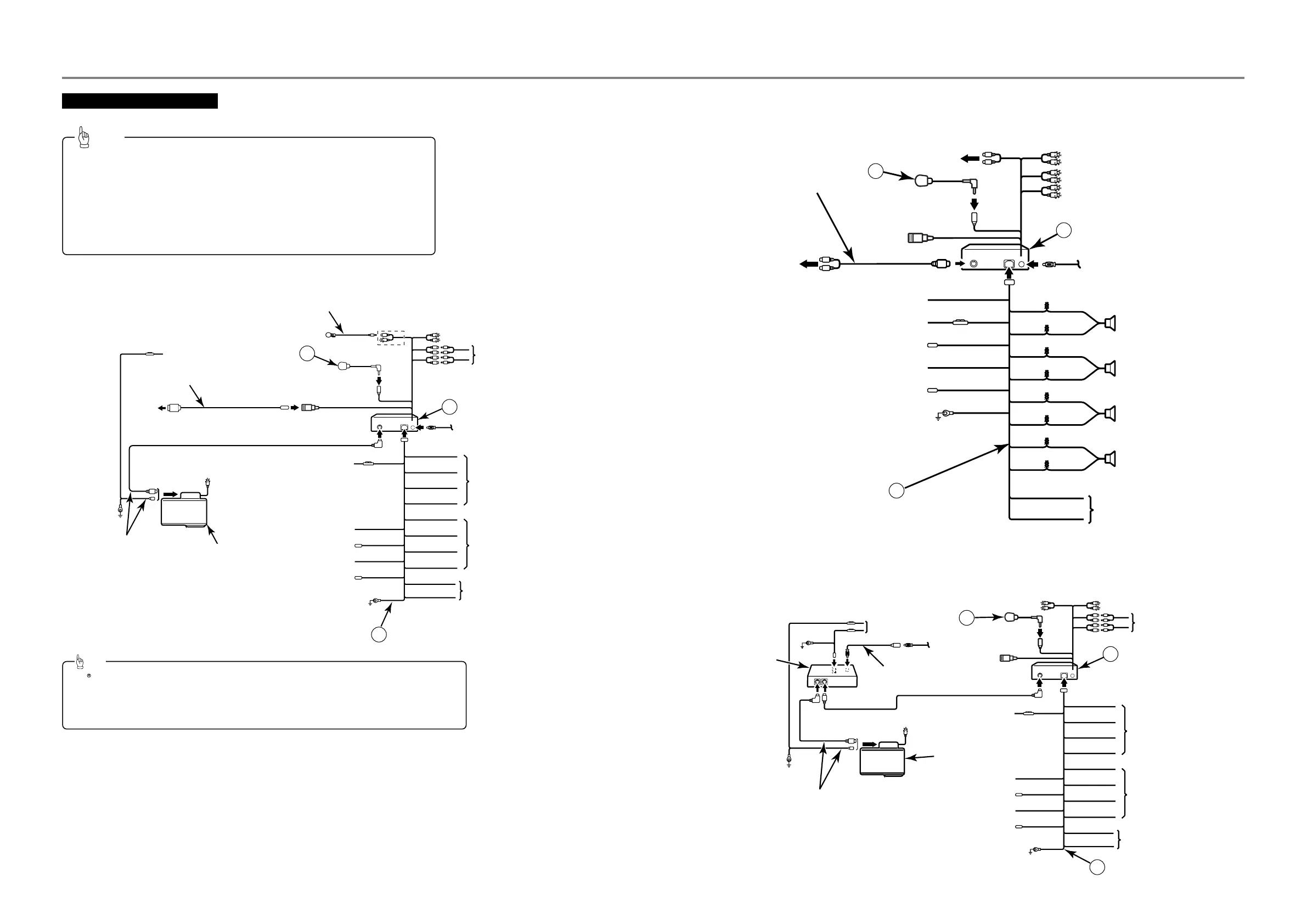
3) CD5030 + HDR109 + CH3083 + Power Amplifier
13P
HDR109 or HDR105
(sold separately)
2P
13P
ANTENNA EXTENSION WIRE
TO SIGNAL INPUT OF AUXLIARY
POWER AMPLIFIER
TO GROUND
TO ACC (Power Supply)
Red
TO HEAD LIGHT SWITCH (Illumination (+) )
Orange/White
TO POWER ANTENNA RELAY (Supply)
Blue
Blue/White
Yellow
Black
16P
ANTENNA PLUG
1
2
TO STEERING REMOTE CONTROL
White
White/Black
Gray
Gray/Black
Green
Green/Black
Purple
Purple/Black
Brown
Brown/Black
NO CONNECTION (Do not remove cap)
CH3083
(sold separately)
INTERCONNECTING WIRES
(supplied with CH3083)
TO GROUND
13P
2P
NO CONNECTION
(Do not remove cap)
NO CONNECTION
(Do not remove cap)
TO GROUND
TO BATTERY+12V
(Permanent Supply)
TO BATTERY+12V
(Permanent Supply)
13P
TO TURN-ON WIRE (Amplifiers, etc.)
INSULATE EACH WIRE WITH NONE
CONDUCTING TAPE SUCH AS
ELECTRICAL TAPE OR ANOTHER
INSULATING METHOD
INSULATE EACH WIRE WITH NONE
CONDUCTING TAPE SUCH AS
ELECTRICAL TAPE OR ANOTHER
INSULATING METHOD
TO USB DEVICE
2)
CD5030
+
EXTERNAL EQUIPMENT (MP3 PLAYER, etc.)
AUX105
(sold separately)
L SIDE
R SIDE
TO THE RCA
OUTPUT
CONNECTORS OF
AN EXTERNAL
EQUIPMENT
S
REAR
SPEAKERS
FRONT
SPEAKERS
TO GROUND
TO ACC (Power Supply)
Red
TO HEAD LIGHT SWITCH (Illumination (+) )
Orange/White
TO POWER ANTENNA RELAY (Supply)
Blue
TO TURN-ON WIRE (Amplifiers, etc.)
Blue/White
TO BATTERY+12V (Permanent Supply)
Yellow
Black
16P
ANTENNA PLUG
1
2
NO CONNECTION (Do not remove cap)
TO STEERING REMOTE CONTROL
White
White/Black
Gray
Gray/Black
Green
Green/Black
Purple
Purple/Black
Brown
Brown/Black
NO CONNECTION (Do not remove cap)
NO CONNECTION (Do not remove cap)
TO USB DEVICE
L SIDE
R SIDE
TO THE RCA OUTPUT CONNECTORS
OF AN EXTERNAL
EQUIPMENT
S
•
Install and connect all of the peripheral units before
connecting them to the main unit.
•
Do not remove any of the protective caps (RCA, etc.) unless
the connectors are in use.
•
Be sure to wrap the connection wires with tape (PVC tape)
to insulate them.
Tip
English
1) CD5030 + iPC-109 + CH3083 + MEI-100 + Power Amplifier
iPC-109
(sold separately)
TO SIGNAL INPUT OF AUXLIARY
POWER AMPLIFIER
L SIDE
TO GROUND
TO ACC (Power Supply)
Red
TO HEAD LIGHT SWITCH
(Illumination (+) )
Orange/White
TO POWER ANTENNA
RELAY (Supply)
Blue
Blue/White
Yellow
Black
16P
To iPod
1
2
TO STEERING REMOTE CONTROL
White
White/Black
Gray
Gray/Black
Green
Green/Black
Purple
Purple/Black
Brown
Brown/Black
NO CONNECTION (Do not remove cap)
CH3083
(sold separately)
INTERCONNECTING
WIRES
(supplied with CH3083)
TO GROUND
13P
2P
NO CONNECTION
(Do not remove cap)
NO CONNECTION
(Do not remove cap)
TO BATTERY+12V
(Permanent Supply)
13P
TO TURN-ON WIRE
(Amplifiers, etc.)
INSULATE EACH WIRE WITH NONE
CONDUCTING TAPE SUCH AS
ELECTRICAL TAPE OR ANOTHER
INSULATING METHOD
INSULATE EACH WIRE WITH NONE
CONDUCTING TAPE SUCH AS
ELECTRICAL TAPE OR ANOTHER
INSULATING METHOD
♦
♦
System connection e
System connection e
xample /
xample /
Ejemplo de cone
Ejemplo de cone
xión del sistema /
xión del sistema /
Ex
Ex
emple de conne
emple de conne
xion du système
xion du système
13P
ANTENNA PLUG
••
iPod is a trademark of Apple Inc., registered in U.S. and other countries.
••
iPod is for legal or right holder-authorized copying only. Don’t steal music.
••
"Made for iPod" means that an electronic accessory has been designed to connect specifically to iPod and has
been certified by the developer to meet Apple performance standards.
••
Apple is not responsible for the operation of this device or its compliance with safety and regulatory standards.
Tip
MEI-100 (sold separately)
TO BATTERY+12V
(Permanent Supply)
15
15
15