Installing the Amplifier
2.
Mounting the Amplifier:After a suitable location has been selected and the
wires routed, the Amplifier can be attached to the Vehicle. Start out by removing
the Polished Aluminum Trim Covers from the top
of
the Amplifier so the Mounting
Hardware and the Wire Connections can be made. Set these aside
in
a safe location
so they can be reinstalled after the Amplifier installation
is
complete. If the Amplifier
location space is limited the Polished end covers may all
be
removed reducing the
overall size
of
the Product.
Lt
Caution
Never use a power tool to drive the mounting hardware while
mounting this product. The Drill Chuck will damage the Heat Sink and Possibly
the Connectors! The wiring can be connected to the Amplifier before or after it is
attached to the Vehicle. Dressing the wiring is easier to do after all connections are
made.
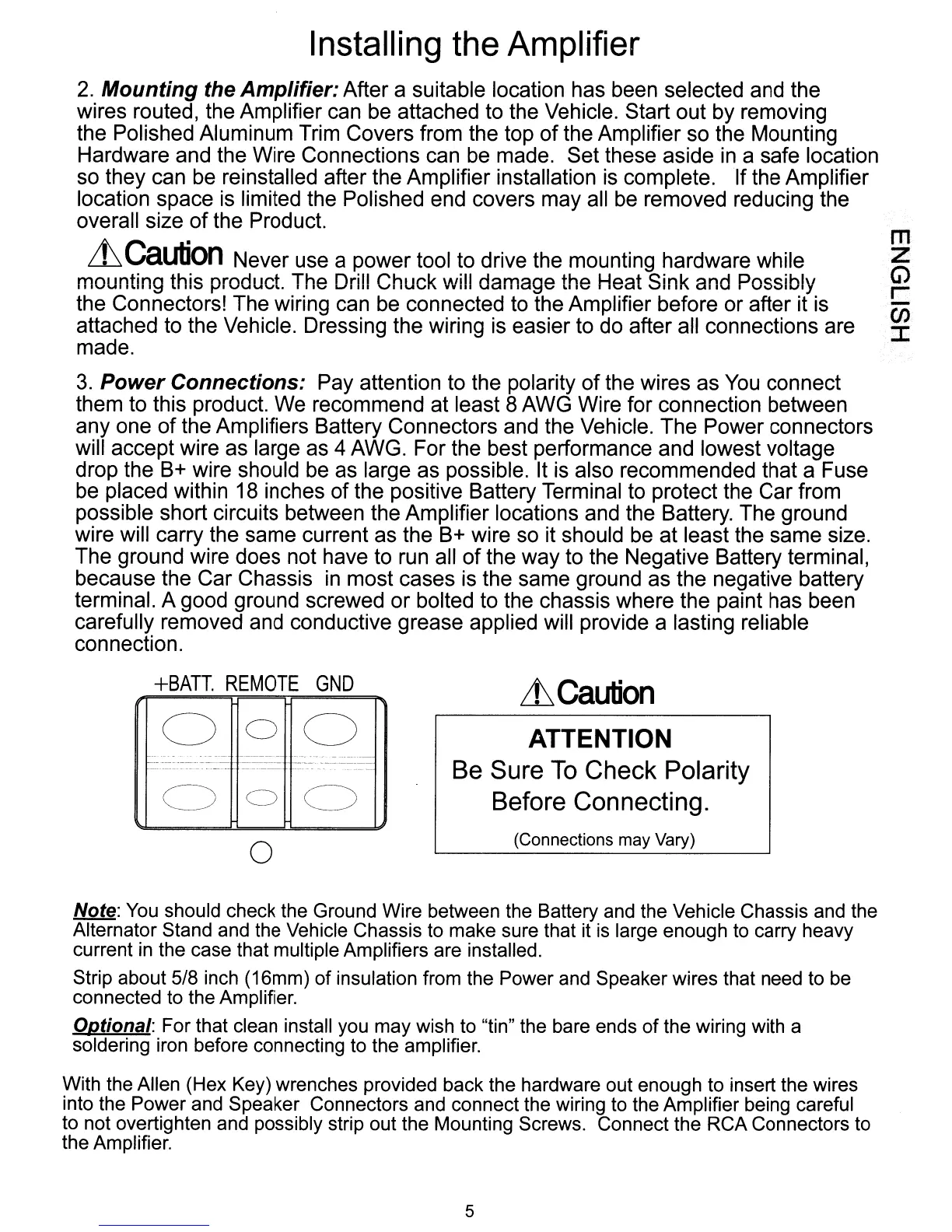
3.
Power Connections: Pay attention to the polarity of the wires as
You
connect
them to this product. We recommend at least 8 AWG Wire for connection between
anyone
of
the Amplifiers Battery Connectors and the Vehicle. The Power connectors
will accept wire as large as 4 AWG. For the best performance and lowest voltage
drop the
B+
wire should
be
as large as possible. It is also recommended that a Fuse
be placed within 18 inches of the positive Battery Terminal to protect the Car from
possible short circuits between the Amplifier locations and the Battery. The ground
wire will carry the same current as the
B+
wire so it should
be
at least the same size.
The ground wire does not have to run all
of
the way to the Negative Battery terminal,
because the Car Chassis
in
most cases is the same ground as the negative battery
terminal. A good ground screwed or bolted to the chassis where the paint has been
carefully removed and conductive grease applied will provide a lasting reliable
connection.
m
z
G)
r-
-
(J)
:c
LtCaution
(Connections may Vary)
ATTENTION
Be Sure
To
Check Polarity
Before Connecting.
---
000
000
o
+BATT.
REMOTE
GND
-------
--
1---
---
._,,"
..
-
_._---_
..
__
._-----~
---------
--------
._-----------
---'_.
- -
_.~_.-
----
---
-
Note:
You
should check the Ground Wire between the Battery and the Vehicle Chassis and the
Alternator Stand and the Vehicle Chassis to make sure that it
is
large enough to carry heavy
current
in
the case that multiple Amplifiers are installed.
Strip about 5/8 inch (16mm)
of
insulation from the Power and Speaker wires that need to be
connected to the Amplifier.
Optional: For that clean install you may wish to "tin" the bare ends
of
the wiring with a
soldering iron before connecting to the amplifier.
With the Allen (Hex Key) wrenches provided back the hardware out enough to insert the wires
into the Power and Speaker Connectors and connect the wiring to the Amplifier being careful
to not overtighten and possibly strip out the Mounting Screws. Connect the RCA Connectors to
the Amplifier.
5

 Loading...