(CONTINUED)
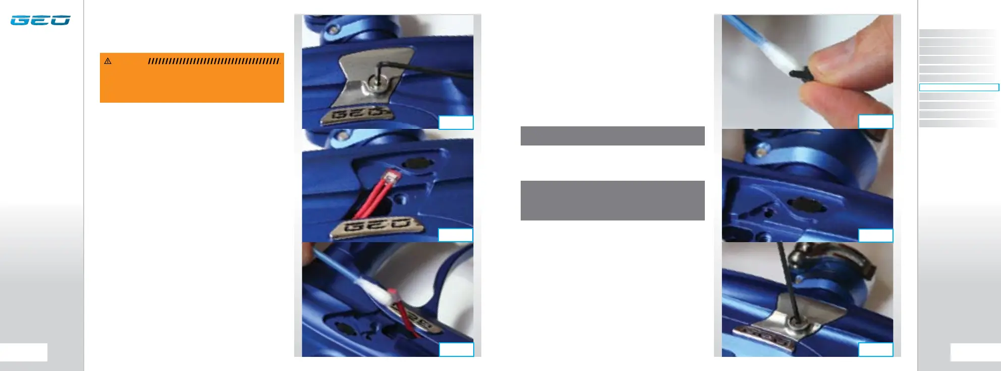
Remove the rubber finger detent and using a dry
cotton bud clean the detent and it’s location point in
the Geo Body. (SEE FIGURE 9.4) Replace the detent back
into the Geo body (SEE FIGURE 9.5) and place the BBSS
back into the designated slot in the body (SEE FIGURE
9.2). Ensure that the sensor is face down in the body i.e
looking into the breech.
Replace the Sensor Cover and using a 5/64" hex key,
replace the Bream Beam Sensor Cover retaining screw
to hold the sensor cover in place (SEE FIGURE 9.6).
Repeat the procedure for opposite side of the Geo.
You have now cleaned your Break Beam Sensor System.
CLEANING THE BREAK BEAM
SENSOR SYSTEM
Undo the retaining screw for the Break Beam Sensor
Cover on the right hand side of the Geo using a 5/64"
(2mm) hex key (SEE FIGURE 9.1).
Remove the Sensor Cover to expose the back of the Break
Beam Sensor unit (SEE FIGURE 9.2). Using a dry cotton
bud, carefully remove any debris, paint or moisture from
the back of the sensor unit and from inside the Sensor
Cover.
Lift the BBSS free from the Geo body and using another
dry cotton bud, remove any grease or debris build-up
from the front of the sensor unit (SEE FIGURE 9.3).
WARNING: DE-GAS YOUR MARKER, DISCHARGING ANY
STORED GAS IN A SAFE DIRECTION, AND REMOVE THE
BARREL, LOADER AND AIR SYSTEM TO MAKE THE MARKER
EASIER TO WORK ON.
NOTE: WHEN CLEANING BREAK BEAM SENSOR SYSTEM
INSPECT CONDITION OF RUBBER FINGER DETENTS AND
REPLACE IF NECESSARY. ENSURE THAT THE RECEIVER
SENSOR (INDICATED BY A RED MARK & RED HEAT SHRINK) IS
LOCATED ON THE RIGHT-HAND SIDE OF THE MARKER BODY.
FIG 9.6
FIG 9.5
FIG 9.4
NOTE: BE CAREFUL NOT TO CROSS-THREAD THE SCREW. DO
NOT OVER TIGHTEN THE SCREW.
FIG 9.2
FIG 9.1
FIG 9.3
CONTENTS
ORIENTATION
QUICK SET-UP
USING YOUR GEO
ADVANCED SET-UP
MENU TREE
MAINTENANCE
FAULT FINDING
SERVICE CENTERS
PARTS LIST
SPARES & ACCESSORIES