USING THE BREAK BEAM
SENSOR SYSTEM
The Break Beam Sensor System is used to detect when
a paintball is ready to fire from the Geo. If no paintball is
ready then the BBSS will inhibit the Geo from firing. This
prevents the Geo from ‘chopping’ paintballs that are
not fully loaded into the marker.
To switch off the Break Beam Sensor System, press and
hold the button for 0.5 second (SEE FIGURE 3.3).
The break beam sensor system indicator on the top right
of the LCD will change from (enabled) to (disabled).
To switch the Break Beam Sensor System back on, press
and hold the button for one second. The indicator will
change back to .
When the Break Beam Sensor System is enabled, the
indicator will change depending on if the system has
detected a ball or not. When no ball has been detected
the indicator looks like this when a ball has been
detected the icon changes to look like this .
Additional features of the Geo’s Break Beam Sensor
System are covered in full on page 24 of this user
manual.
NOTE: WHEN THE GEO IS TURNED ON, THE BREAK BEAM
SENSOR SYSTEM IS AUTOMATICALLY ENABLED
SWITCHING ON THE GEO
To switch on the Geo press the button twice in
quick succession, referred to elsewhere in this manual
as ‘double-clicking’. The Geo can also be switched on by
pushing and holding the button (FIGURE 3.1).
SWITCHING OFF THE GEO
Press and hold the button until the display shows
OFF? Release the button and re-press it to turn off
the Geo. Alternatively when the display reads OFF?, you
can pull the trigger once to turn off the Geo.
FIRING THE GEO
Pull the trigger to fire the Geo. The entire firing
sequence is controlled electronically by the Geo circuit
board, enabling any user to easily achieve high rates
of fire.
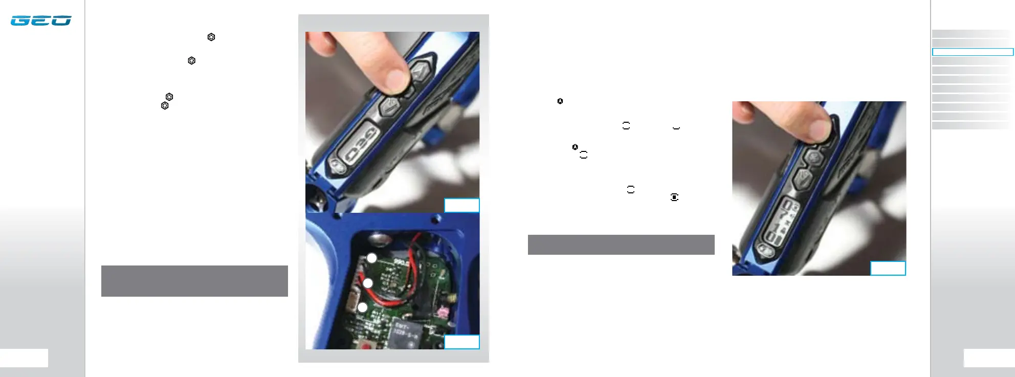
THE GEO CIRCUIT BOARD
There are three sockets on the Geo Circuit board two of
which are occupied by the BBSS Connector (A) and the
Geo Solenoid (B). The third socket on the board (C) is
the Auxiliary socket to which third party products such
as loaders and RF transmitters can be connected using
the relevant wiring harness (SEE FIGURE 3.2).
NOTE: WHEN THE GEO IS TURNED ON, THE AUXILIARY
SOCKET IS AUTOMATICALLY SWITCHED ON AND CANNOT BE
SWITCHED OFF
FIG 3.3
FIG 3.2
FIG 3.1
C
A
B
CONTENTS
ORIENTATION
QUICK SET-UP
USING YOUR GEO
ADVANCED SET-UP
MENU TREE
MAINTENANCE
FAULT FINDING
SERVICE CENTERS
PARTS LIST
SPARES & ACCESSORIES