J
Jennifer ChristensenAug 12, 2025
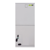
What to do if my Ecoer Heat Pump system cannot cool well?
- DDylan JenkinsAug 12, 2025
If your Ecoer Heat Pump system isn't cooling well, several factors could be the cause. It could be due to high or low outside temperatures, which activate a normal protection control to limit RPS. Other potential causes include a dirty air filter or a blocked outlet of the indoor unit (in which case you should replace the air filter and remove any obstacles), too little refrigerant in the system (check the refrigerant amount or for any leaks), or a blocked refrigerant in the condenser coil (counterclockwise the TXV, ensuring the refrigerant coefficient is 0.6).