Do you have a question about the Ecoer EAHAEC-36 and is the answer not in the manual?
General guidelines to prevent injury or damage to the unit.
Procedures for handling accidents or emergencies.
Safety guidelines for the pre-installation and installation phases.
Safety guidelines for operating and maintaining the unit.
Servicing procedures concerning flammable refrigerants and safety.
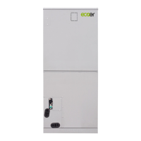
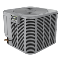
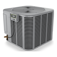
Details on specific indoor and outdoor unit model numbers.
Visual representations of the indoor and outdoor units.
Key features and capabilities of the indoor unit.
Physical dimensions and opening sizes of the indoor unit.
Identification of internal components of the indoor unit.
Recommended space and clearance for servicing the indoor unit.
List of included installation parts and accessories.
Graphs showing fan airflow rate vs. external static pressure.
Sound level data for the indoor unit at different frequencies.
Electrical specifications for the indoor unit.
Diagrams illustrating indoor unit electrical connections.
Explanation of micro-switch and DIP switch functions.
Introduction to micro-switch functions and operation.
Details on DIP switch settings for unit control.
Physical dimensions of the outdoor unit.
Recommended space and clearance for outdoor unit installation.
Factors to adjust capacity based on height difference.
Sound level data for the outdoor unit at different frequencies.
Diagrams illustrating the refrigerant flow within the system.
Diagrams illustrating outdoor unit electrical connections.
General steps and sequence for unit installation.
Guidelines for choosing the optimal installation site.
Procedures for installing the indoor unit (Air Handler Unit).
Standard installation steps for the indoor unit.
Instructions for specific installation configurations like reversing.
Steps for installing the optional electric auxiliary heat module.
Procedures for installing the outdoor unit.
Required clearance and space around the outdoor unit.
Mounting hole specifications and bolt pitch for the outdoor unit.
Securing the outdoor unit during installation.
Procedures for installing the condensate drainage pipe.
Basic principles for proper drainage pipe installation.
Important considerations for drainage pipe setup and layout.
Guidelines for installing refrigerant piping.
Guidelines for maximum refrigerant pipe length and elevation.
Steps for connecting refrigerant pipes.
Procedures for vacuum drying and checking for leaks.
Reasons for performing vacuum drying on the system.
Criteria for selecting an appropriate vacuum pump.
Step-by-step guide for performing vacuum drying.
Procedure for adding refrigerant to the system.
General guidelines for insulation engineering.
Methods for insulating refrigerant pipes correctly.
Guidelines for insulating drainage pipes to prevent condensation.
Key considerations for electrical wiring installation.
Important points for proper electrical wiring.
Different methods for electrical connections and wiring.
Wiring instructions for optional functions like overflow switches.
Explanation of unit control logic and connector purposes.
Procedures and checks for testing the installed unit.
Confirmation that installation is complete before testing.
Verification steps required before starting the test operation.
Step-by-step guide for performing the test run.
Procedure to test the unit's drainage system.
Checks to perform after initial installation.
Steps and procedures for recharging refrigerant.
Procedures for re-installing components or the system.
Procedure for collecting refrigerant from the indoor unit.
Evacuation procedure for the entire system from the outdoor unit.
Description of the unit's display functions and indicators.
Protection mechanisms and auto-shutoff features.
Fundamental operational modes and functions of the unit.
Operation details specific to the cooling mode.
Operation details for heating mode in heat pump units.
How the unit operates in defrosting mode.
Unit's operation in automatic mode based on conditions.
Unit's operation in dry mode for humidity control.
How to activate and use forced operation modes.
Explanation of timer settings and operation.
How the sleep mode functions to adjust temperature and fan speed.
Functionality of the auto-restart feature after power loss.
Overview of functions available via the remote controller.
Features and functions of the LCD wired remote controller.
Explanation of the remote controller's display screen elements.
Installation guide for the wired remote controller.
Important safety warnings before performing troubleshooting.
General guidance for diagnosing and resolving unit issues.
List of indoor unit error codes and their meanings.
List of outdoor unit error codes and their meanings.
How to check unit status using the outdoor PCB.
How to access unit information via the remote controller.
Troubleshooting common issues without specific error codes.
Troubleshooting common issues via remote interaction.
Troubleshooting common issues during field service.
Recommends parts based on error codes for quick fixes.
Detailed troubleshooting for specific error codes.
Solves EEPROM parameter errors on indoor/outdoor PCBs.
Addresses communication errors between indoor and outdoor units.
Solves errors related to fan speed and motor failures.
Solves errors related to temperature sensors.
Addresses refrigerant leakage detection errors.
Solves errors related to water level alarms.
Solves IPM malfunction and over-current protection errors.
Addresses various voltage protection errors.
Solves errors related to inverter compressor drive.
Addresses low pressure protection errors.
Solves compressor/IPM high temperature protection errors.
Addresses general outdoor unit malfunctions.
Solves communication errors between PCBs and IPM.
Solves current overload and speed errors.
Addresses PFC module protection errors.
Solves phase failure errors in outdoor DC fan motors.
Addresses compressor phase protection errors.
Solves IR chip drive failure errors.
Explains the low ambient temperature protection function.
Solves IPM module temperature sensor faults.
Addresses high pressure protection errors.
Solves condenser high temperature protection errors.
Addresses compressor discharge temperature protection.
Solves communication errors between indoor chips.
Solves communication issues between adapter and outdoor boards.
Addresses errors due to mismatched indoor/outdoor units.
Solves compressor current sampling circuit failures.
Addresses communication errors between wired controller and unit.
Procedures for checking various components.
How to check temperature sensor resistance.
Procedure to check compressor windings resistance.
How to check IPM continuity.
Steps to check the 4-way valve operation.
Procedure to check the Electronic Expansion Valve (EEV).
How to check the fuse for the auxiliary heat module.
Steps for disassembling electrical components of the indoor unit.
Procedure for disassembling the fan motor and fan.
Steps for disassembling the evaporator assembly.
Procedure for disassembling the optional auxiliary heat module.
Table of outdoor unit models and their corresponding components.
General procedures for disassembling the outdoor unit.
Steps for removing the outdoor unit panels.
Steps for disassembling electrical parts like PCBs.
Procedure for disassembling the outdoor unit fan assembly.
Steps for disassembling the outdoor unit fan motor.
Procedure for removing the sound blanket.
Steps to disassemble the four-way valve.
Procedure for disassembling the compressor.
Resistance values for temperature sensors at different temperatures.
Resistance values for TP temperature sensor at different temperatures.
Pressure readings on service ports for cooling and heating.
| Cooling Capacity (BTU) | 36, 000 |
|---|---|
| SEER | Up to 20 |
| HSPF | 10 |
| Heating Capacity (BTU) | 36, 000 |
| Sound Level (dB) | 56 |
| Refrigerant | R410A |
| Power Supply | 208-230V, 1Ph, 60Hz |