113/157
SDi Decades Extreme Service Manual www.ecoer.com
May. 2023Manufacturer reserves the right to change specifications or designs without notice.
8.7.15 PC 0F(PFC module protection diagnosis and solution)
Description: When the voltage signal that IPM send to compressor drive chip is abnormal, the LED displays
the failure code and the AC turns off.
Recommended parts to prepare:
• Connection wires
• Inductance
• Outdoor main PCB
• PFC module
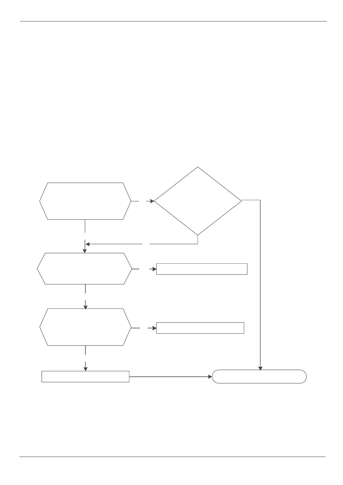
Troubleshooting and repair:
At first test the resistance between every two ports of U, V, W of IPM and P, N. If any result of them is 0 or close to
0, the IPM is defective. Otherwise, please follow the procedure below:
Check whether the
connecting line between
main board and the PFC
module is connected tightly
Yes
Measure whether the voltage
between P and N is normal
refer to the Index?
Check whether the
inductance of PFC module
is good? If the inductance is
good, the resistance of the
two ports is 0
Yes
Replace the inductance
No
Connect it tightly, check
normal or not
Replace the outdoor main board
Yes
Yes
No
No
Replace the PFC module
Trouble is solved
Yes