EasyManua.ls Logo

Ecoer EAHAEC-36 - 10.2.2 Electrical Parts

Ecoer EAHAEC-36
157 pages
Print Icon
To Next Page IconTo Next Page
To Previous Page IconTo Previous Page
Loading...
142/157
SDi Decades Extreme Service Manual www.ecoer.com
May. 2023Manufacturer reserves the right to change specifications or designs without notice.
WARING: Antistatic gloves must be worn when you disassemble the electronic box.
Note: Remove the air outlet grille(refer to 10.2.1 Panel Plate) before disassembling electrical
parts.
10.2.2 Electrical Parts
PCB board
Note: This section is for reference only. Actual unit appearance may vary.
Procedure
Illustration
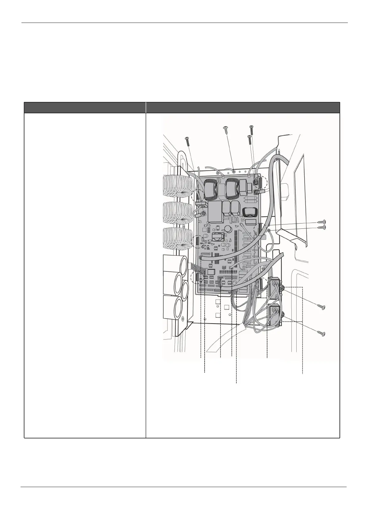
1) Remove 2 screws to disconnect the
power supply wires. (see ODU_
PCB_1)
2) Remove 3 screws to disconnect
ground wires. (see ODU_
PCB_1)
3) Disconnect the wires connected to
main control board. (see ODU_
PCB_1)
4) Disconnect the wires between main
control board and IPM module board.
(see ODU_ PCB_1)
5) Remove the 4 screws and unfix
the 6 hooks and then remove the
main control board.(see ODU_
PCB_1)
6) Remove 1 screw to remove the fan
motor capacitor(1 screw for each
capacitor).(see ODU_ PCB_1).
ODU_ PCB_1
connect to indoor unit
connect to IPM
T3&T4 TP
low&high pressure switch
AC Fan motors
Fan motor capacitors

Related product manuals