Function
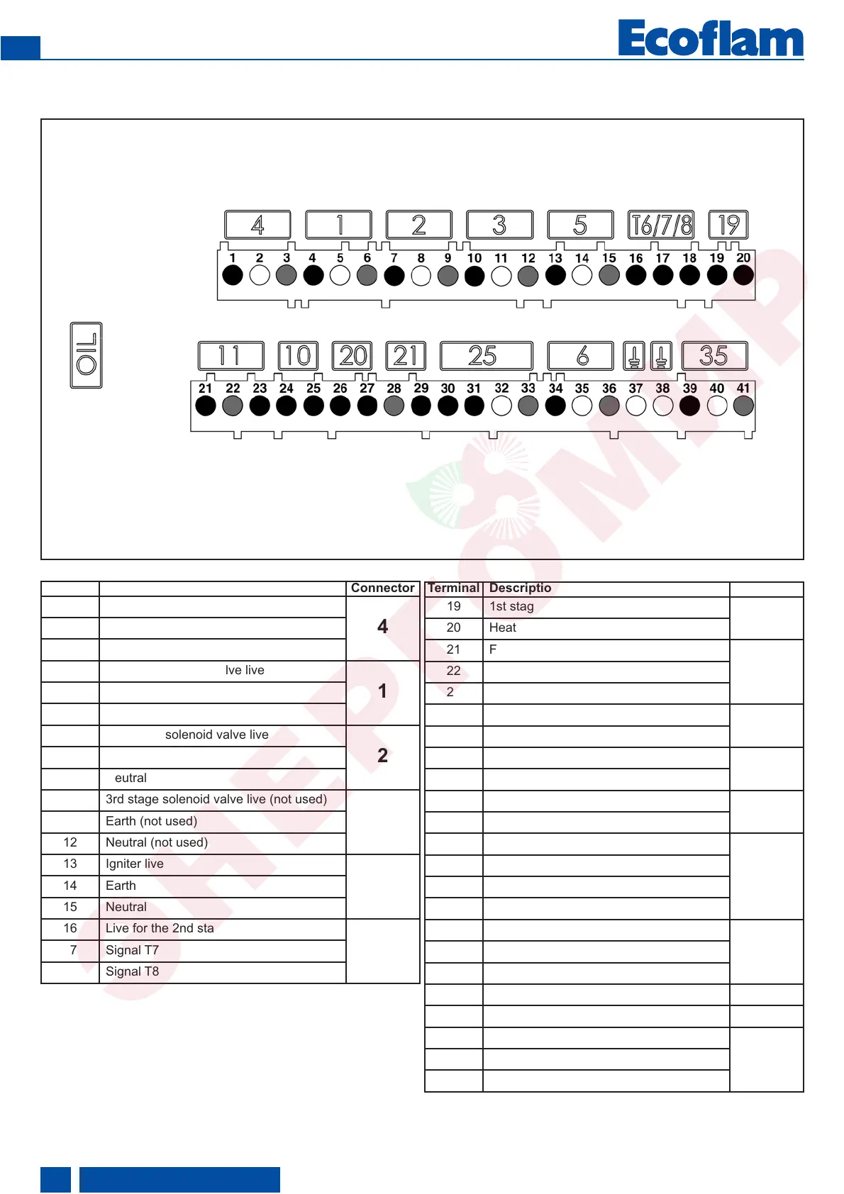
- Terminal allocation chart 230 Volt connection
Terminal Description Connector
1 Burner motor phase
4
2 Earth
3 Neutral
4 1st stage solenoid valve live
1
Earth5
Neutral6
2nd stage solenoid valve live7
2
Earth8
Neutral9
3rd stage solenoid valve live (not used)10
3
Earth (not used)11
Neutral (not used)12
13 Igniter live
5
14 Earth
15 Neutral
16 Live for the 2nd stage thermostat
T6/7/8
17 Signal T7
18 Signal T8
Terminal Description Connector
19 1st stage thermostat live (T1)
19
20 Heating request signal (option T2)
21 Flame monitoring signal
11
22 Earth
23 Live
24 Not used
10
25 Not used
26 Live
20
27 Remote unlocking signal
28 Neutral
21
29 Signal fault live
30 Live
25
31 Preheater/release contact
32 Earth
33 Neutral
34 Live L1
6
35 Earth
36 Neutral
37 Earth
38 Earth
39 Pump unit live
35
40 Earth
41 Neutral
420010492200
EN
 Loading...