EN
420010492200
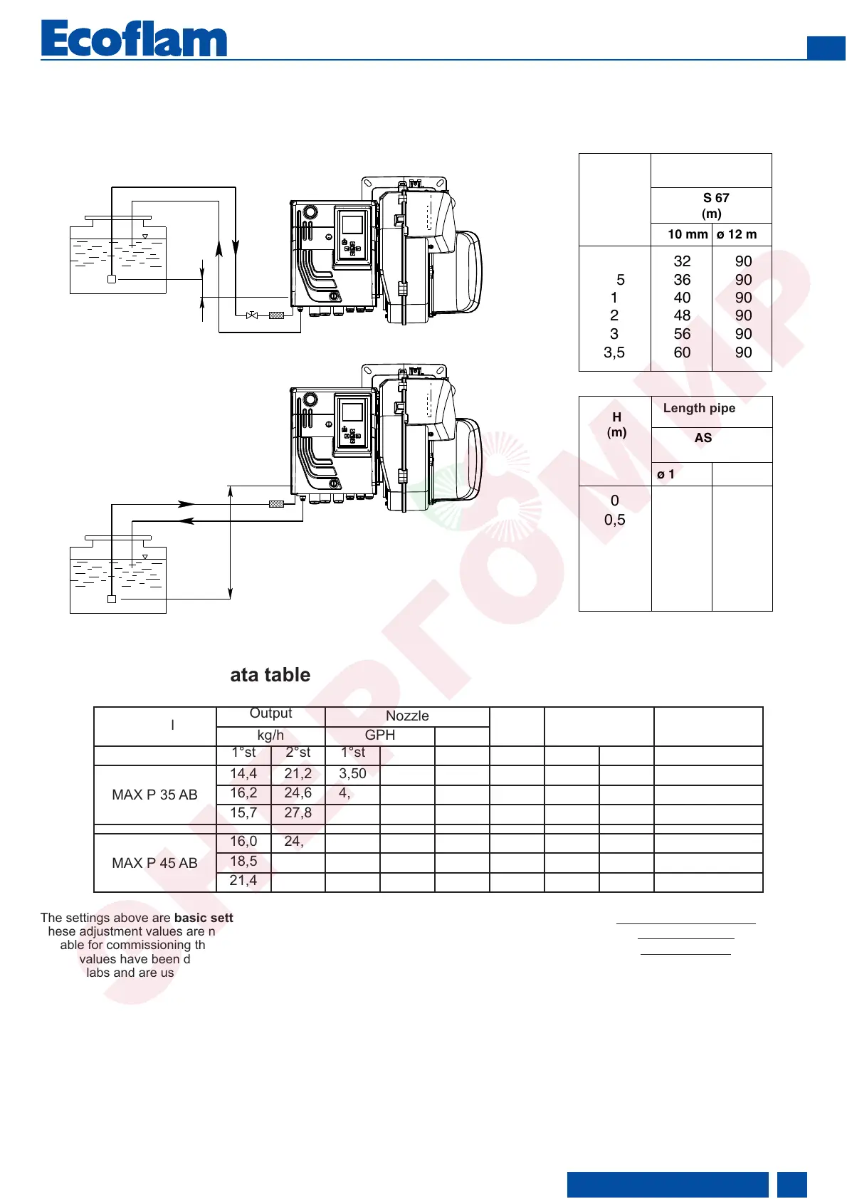
Installation - Oil feeding and suction line
Two-pipe siphon feed system
Two-pipe lift system
Length pipe (m)
Length pipe (m)
FEEDING LINE WITH SUNTEC AS 67 B
Start up
- Setting data table
Model
Output
Nozzle
Pump Air Setting Head Setting
kg/h GPH Spray
1°st 2°st 1°st 2°st bar 1°st 2°st
MAX P 35 AB
14,4 21,2 3,50 1,50 60°S 12 30° 40° 4
16,2 24,6 4,00 2,00 60°S 12 30° 55° 3
15,7 27,8 4,00 3,00 60°S 11,4 30° 70° 2
MAX P 45 AB
16,0 24,6 4,00 2,00 60°S 12 30° 36° 4
18,5 32,3 4,50 3,50 60°S 12 27° 63° 3
21,4 39,8 5,00 4,50 60°S 14 30° 90° 2
The settings above are basic settings.
These adjustment values are normally
suitable for commissioning the burner.
These values have been determined in
our test labs and are useful for the first
switch-on as final setting must be done
using a combustion analyzer.
Favourable combustion values can be
achieved using the following nozzles:
DANFOSS H÷S 80°÷60°
DELAVAN W 60°
STEINEN S 60°
 Loading...