SmartZone EQUIPMENT STAGING
1ST STAGE
-10⁰
-25⁰
HI TEMP CUT-OUT
2
nd
STAGE CUT-IN
2
nd
STAGE CUT-IN
(3-Minute
Minimum Run
Time)
(Starts when first call
for heat is made)
GAS/ELECTRIC HEATING
135⁰
110⁰
125⁰
RC
RH
COM
W2
O/B
Y1
Y2
G
EQUIPMENT
W1
EH
RC
RH
COM
W2
O/B
Y1
Y2
G
EQUIPMENT
W1
EH
2ND STAGE
12
8
4
0
TIME (Minutes)
Adjustable Range:
(125 to 150°F)
1ST STAGE
-15⁰
HI TEMP CUT-OUT
2
nd
STAGE CUT-OUT
2
nd
STAGE CUT-IN
AUX. HEAT CUT-IN
(Starts when first call
for heat is made)
HEAT PUMP (NORMAL) – HEATING [ELECTRIC AUX.]
115⁰
120⁰
90⁰
105⁰
100⁰
AUX. HEAT CUT-OUT
0
2
4
TIME (Minutes)
Adjustable Range: (110 to 125°F)
►W1 de-energizes at a supply air
temp warmer than HI temp cut-out
and will re-energize after 3 min if
supply temp has fallen lower (cooler)
than HI temp (Default: 135°F)
►W2 energizes at a supply air temp
cooler than 25⁰ less than HI temp cut-
out after 8 minutes run time of W1 only.
(Default: 135 - 25 = 110 or cooler)
►W2 de-energizes at supply air
temp warmer than 10⁰ less than HI
temp cut-out after 3 min of minimum
run time.
(Default: 135 - 10 = 125 or warmer)
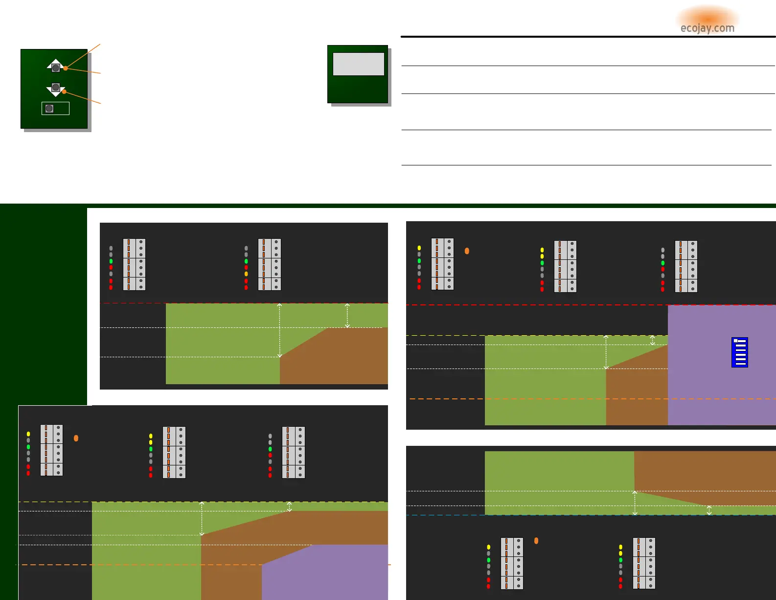
The SmartZone controls equipment
staging automatically based on
time and supply air temperature.
(This temperature is read by the
SUPPLY AIR TEMP SENSOR – SEE
previous page for proper
installation) NOTE:
Without this
sensor installed, the SmartZone will
NOT run 2
nd
stage or operate any
dampers.
The charts in this section illustrate
this correlation between TIME,
TEMPERATURE, & STAGING
(
FACTORY DEFAULTS SHOWN IN
CHARTS
)
Time and temperature settings will
vary according to the type of
equipment SmartZone is configured
for and the HI/LO temp limit
settings used. Staging will occur
ONLY when the minimum run-time
and temperature range conditions
are met. The factory default
settings for temperature cut-in and
cut-out are adjustable. (SEE HIGH
and LOW LIMIT ADJUST section
above)
1
ST
STAGE
2
nd
STAGE
SUPPLY AIR TEMP (⁰F) DEFAULT Values
SUPPLY AIR TEMP (⁰F) DEFAULT Values
RC
RH
COM
W2
O/B
Y1
Y2
G
EQUIPMENT
W1
EH
►Y2 energizes at a supply
temp 15⁰ less than HI temp
cut-out (or cooler) after a 4
minute run time of Y1 only.
(Default: 120⁰ - 15⁰ = 105⁰F
or cooler Y2 energizes)
►Y2 de-energizes at a supply
temp of 5⁰ less than HI temp
cut-out (or warmer) after 3 min
of minimum run time.
(Default: 120⁰ - 5⁰ = 115⁰F or
above Y2 de-energizes)
2
nd
STAGE
RC
RH
COM
W2
O/B
Y1
Y2
G
EQUIPMENT
W1
EH
1
ST
STAGE
►Y1 and G equipment
terminals energize when any
thermostat calls for heat.
NOTE: B will also energize
if DIP SWITCH #2 set to B
►Y1 de-energizes at a supply
temp warmer than (above) HI
temp cut-out and will re-
energize after 3 min if supply
temp has fallen lower (cooler)
than HI temp (Default: 120⁰F)
RC
RH
COM
W2
O/B
Y1
Y2
G
EQUIPMENT
W1
EH
AUX. HEAT
►W1 [Auxiliary Heat]
energizes while Y1&Y2
de-energize at a supply
temp cooler than 90⁰F
after 6 minutes run time
of Y1 & Y2 only.
►W1 [Auxiliary Heat]
de-energizes at a
supply temp of 100⁰F
or warmer (NON-
ADJUSTABLE)
►W1 & G energize when any
thermostat calls for heat.
G will energize immediately if DIP
SWITCH #5 is set to “ELECTRIC”.
If set to the default of “GAS”, G will
energize after 90 seconds.
*
Adjustable Range:
(90 to 94°F)
2ND STAGE
(3-Minute Minimum
Run Time)
-5⁰
6
AUX HEAT
8
HIGH AND LOW LIMIT ADJUST
5
1ST STAGE 2ND STAGE
-15⁰
-5⁰
HI TEMP CUT-OUT
2
nd
STAGE CUT-OUT
2
nd
STAGE CUT-IN
(3-Minute Minimum
Run Time)
(Starts when first call
for heat is made)
HEAT PUMP (DUAL FUEL) – HEATING [GAS AUX.]
115⁰
120⁰
105⁰
AUX. HEAT
(Once AUX Heat has started
in Dual Fuel mode, it will
continue to run until all heat
calls are satisfied.)
135⁰
GAS AUX. HEAT HI TEMP CUT-OUT
0
2 4
6
8
TIME (Minutes)
1ST STAGE
+10⁰
LOW TEMP CUT-OUT
2
nd
STAGE CUT-IN
2
nd
STAGE CUT-OUT
(3-Minute Minimum
Run Time)
(Starts when first call
for cool is made)
COOLING ALL
58⁰
48⁰
RC
RH
COM
W2
O/B
Y1
Y2
G
EQUIPMENT
W1
EH
RC
RH
COM
W2
O/B
Y1
Y2
G
EQUIPMENT
W1
EH
►Y1 de-energizes at a supply air
temp lower (cooler) than the LO
temp cut-out and will re-energize
after 3 min if supply temp has risen
above (warmer) than LO temp.
(Default: 48°F or cooler)
►Y1 and G energize when any
thermostat calls for cool.
►Y2 energizes at a supply air temp
higher (warmer) than 10⁰ more than
LO temp cut-out after 8 minutes run
time of Y1 only.
(Default: 48⁰ + 10⁰ = 58⁰F or warmer)
►Y2 de-energizes at a supply air temp
cooler than 4⁰ more than LO temp cut-out
after 3 min of minimum run time.
(Default: 48⁰ + 4⁰ = 52⁰F or cooler Y2 de-
energizes)
2ND STAGE
128
4
0
TIME (Minutes)
(NOTE: O will also energize if
DIP SWITCH
# 1 set to HEAT PUMP and
#2 set to O)
+4⁰
52⁰
Adjustable Range: (41 to 55°F)
Adjustable Range: (110 to 125°F)
**
AUTO CHANGEOVER
ADJUST SETTINGS
STAT
TYPE
PRESS & release the ▲ ”UP” arrow button when the display is showing SUPPLY temperature. The “HI
TEMP” indicator will flash and the digits will show the currently set temperature. This high limit cut-out
can be adjusted up or down using the ▲▼buttons. See EQUIPMENT STAGING below for more details.
PRESS & release the ▼ ”DOWN” arrow button when the display is showing SUPPLY temperature. The “LO
TEMP” indicator will flash and the digits will show the currently set temperature. This low limit cut-out can
be adjusted up or down using the ▲▼buttons. See EQUIPMENT STAGING below for more details.
SET HIGH TEMP LIMIT (CUT-OUT)
SET LOW TEMP LIMIT (CUT-OUT)
IMPORTANT NOTE:
Changing either the LOW or HIGH temp limit will also affect the staging
cut-in and cut-out temperatures settings. Adjusting these can cause staging to occur sooner or
later as needed. See EQUIPMENT STAGING below for more details about each scenario.
PRESS & HOLD the ▲ ”UP” arrow button for 5 seconds when the display is showing SUPPLY
temperature. When released the “HI LIMIT” and “DELAY” indicators will flash and the digits will
show the currently set temperature (DEFAULT = 90, adjustable from 90 to 94 using ▲▼buttons).
AUX. HEAT CUT-IN
See EQUIPMENT STAGING below for more details. For protection, SmartZone will not allow the EQUIPMENT to run above or below these settable limits.
With the SmartZone system, it is possible to have a zone(s) calling for cool and another zone(s) calling for heat. These are called opposing calls. When the
equipment has an active call running and SmartZone receives an 'opposing call' from another zone(s), the existing active mode running on the equipment will be
limited to a maximum run time of 15 minutes from the time the first opposing mode call was received. If the active mode does not satisfy the calling zone(s) in this
15 minute interval SmartZone will initiate a CHANGEOVER process de-energizing the active mode and initiating a 3 minute PURGE (see page 3 for more about
PURGE). During PURGE, all dampers open during the previously active mode remain open and the fan remains energized to neutralize the supply air temperature
before energizing the opposing call mode on the equipment CHANGEOVER process.
NOTE: SET DIP SWITCH #3
to GAS/ELECT temporarily to
adjust this HI LIMIT CUT-
OUT. Make sure to set it
back to HEAT PUMP when
adjustment is complete.
**
RC
RH
COM
W2
O/B
Y1
Y2
G
EQUIPMENT
W1
EH
►Y2 energizes at a supply
temp 15⁰ less than HI temp
cut-out (or cooler) after a 4
minute run time of Y1 only.
(Default: 120⁰ - 15⁰ = 105⁰F
or cooler Y2 energizes)
►Y2 de-energizes at a supply
temp of 5⁰ less than HI temp
cut-out (or warmer) after 3 min
of minimum run time.
(Default: 120⁰ - 5⁰ = 115⁰F or
above Y2 de-energizes)
2
nd
STAGE
RC
RH
COM
W2
O/B
Y1
Y2
G
EQUIPMENT
W1
EH
1
ST
STAGE
►Y1 and G equipment
terminals energize when any
thermostat calls for heat.
NOTE: B will also energize
if DIP SWITCH #2 set to B
►Y1 de-energizes at a supply
temp warmer than (above) HI
temp cut-out and will re-
energize after 3 min if supply
temp has fallen lower (cooler)
than HI temp (Default: 120⁰F)
RC
RH
COM
W2
O/B
Y1
Y2
G
EQUIPMENT
W1
EH
AUX. HEAT
►W1 [Auxiliary Heat]
energizes AND Y1 & Y2
will de-energize at a
supply temp cooler than
90⁰F after 6 minutes run
time of Y1 & Y2.
►W1 [Auxiliary Heat]
remains energized until all
heat calls are satisfied or the
supply temp gets warmer
than “GAS/ELECTRIC” HI
limit (Default: 135⁰F)
AUX. HEAT CUT-IN
90⁰
SUPPLY AIR TEMP (⁰F) DEFAULT Values
1
ST
STAGE
SUPPLY AIR TEMP (⁰F) DEFAULT Values
2
nd
STAGE
Adjustable Range:
(90 to 94°F)
Adjustable Range: (125 to 150°F)
HEAT PUMP
B
DUAL FUEL
ELECTRIC
GAS/ELECT
RVS. VLV. O
NORMAL
FAN GAS
LOCKOUT2
nd
STAGE
SMART LINK
ZONES (1 – 4)
ZONES (5 – 8)
SE
HI TEMP
LO TEMP
SUPPLY
PURGEDELAY ECO
TO SAVE SETTINGS,
wait for display to
show “St” (STORE)
4
TROUBLESHOOTING
SYMPTOM POSSIBLE CAUSE
DISPLAY IS BLANK
►VERIFY OUTPUT OF TRANSFORMER INCLUDING CONNECTIONS TO PRIMARY, SECONDARY AND ZONE PANEL POWER CONNECTOR
►CHECK TRANSFORMER FUSE
►CHECK SMARTZONE FUSE (SPARE INCLUDED)
►CHECK FOR SHORT IN WIRING CONNECTED TO SMARTZONE (REMOVE THERMOSTAT, DAMPER, & EQUIPMENT WIRES)
DISPLAY READS “- - “
►SUPPLY AIR TEMP SENSOR IS NOT CONNECTED TO SMARTZONE
►SUPPLY AIR TEMP SENSOR HAS A LOOSE CONNECTION
►DIP SWITCH # 6 IS SET TO “ZONE 5-8” → THIS IS ONLY FOR 8 ZONE APPLICATIONS
►SUPPLY AIR TEMP SENSOR IS DEFECTIVE
THERMOSTAT INDICATES CALL BUT
EQUIPMENT TERMINALS NOT RESPONDING
►SMARTZONE IS IN “DELAY” OR “PURGE” - DISPLAY SHOULD BE COUNTING DOWN IN SECONDS TIME REMAINING (3 MIN)
►AN INCOMPATIBLE THERMOSTAT IS CONNECTED TO SMARTZONE (THERMOSTATS WITH A COMMON SHOULD BE USED)
►WIRING BETWEEN SMARTZONE AND EQUIPMENT COULD BE DAMAGED OR NOT SECURELY CONNECTED
►TRANSFORMER TO POWER SMARTZONE & COMPONENTS COULD HAVE INNSUFFICIENT VA RATING
►PRIMARY POWERING SMARTZONE TRANSFORMER COULD BE BEYOND CAPACITY (USE DEDICATED CIRCUIT FROM BREAKER)
SMARTZONE EQUIPMENT INDICATES HEAT/COOL
CALL BUT EQUIPMENT NOT ENERGIZING
►RC/RH JUMPER MISSING OR INSTALLED ON ONLY ONE PIN
►EQUIPMENT TRANSFORMER NOT CONNECTED, SHORTED OR LOOSE CONNECTION (ALSO CHECK FUSE)
►SMARTZONE TRANSFORMER INSUFFICIENT VA (SEE PAGE 2)
►ECO MODE ENERGIZED: “ECO” WILL BE ILLUMINATED ON DISPLAY (SEE PAGE 2)
►SMARTZONE HAS DEFECTIVE EQUIPMENT RELAY (CALL FOR RMA VERIFICATION)
HEAT PUMP ONLY: SMARTZONE ENERGIZES
COOLING WHEN ZONES CALL FOR HEAT
(O/B DOESN‟T ENERGIZE)
►”STAT TYPE” SETTING DOES NOT MATCH THERMOSTAT BEING USED (PRESS STAT TYPE BUTTON – PAGE 6)
►AN INCOMPATIBLE THERMOSTAT IS CONNECTED TO SMARTZONE (THERMOSTATS WITH A COMMON SHOULD BE USED)
►DIP SWITCH # 2 (REVERSING VALVE) SET TO OPPOSITE MODE “O” OR “B”
►WIRING BETWEEN SMARTZONE O/B TERMINAL AND EQUIPMENT COULD BE DAMAGED OR NOT SECURELY CONNECTED (CHECK VOLTAGE)
MORE INFO ON
TROUBLESHOOTING
ecojay.com
ecojay.com
 Loading...