BYPASS Setup
& Sizing on
NEXT PAGE
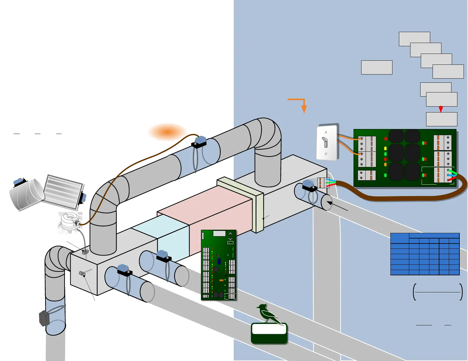
RECTANGULAR
DSEP
ZONE
SUPPLY
DAMPER
DAMPER
DAMPER
ZONE
SUPPLY
ZONE
SUPPLY
BYPASS
DAMPER
BYPASS
DUCT
FRESH AIR
DAMPER
SUPPLY
TEMP.
SENSOR
EVAPORATOR
COIL
GAS or ELECTRIC
FURNACE
SUPPLY
PLENUM
RETURN AIR
PLENUM
FILTER
RETURN AIR Problems with zoning
can occur when the return air registers
or duct are undersized. Not enough
CFM will flow through the equipment to
satisfy the velocity requirements when
all dampers are open. To ensure the
Return Air is large enough, verify that
its surface area is sufficient to pass FULL
SPEED blower CFM.
Ensure ALL zones have unrestricted
airflow path “back” to a return air grill
equivalent to the zone CFM.
AIR NOISE should be always be minimized and in a zoning system with opening & closing dampers it can be more challenging. To minimize noise and maintain
adequate throw, zone duct should be designed to provide 600 to 700 FPM velocity airflow. This can be achieved by providing large enough ducts/dampers to supply the
volume (CFM) of air needed for the zone. Use the “Normal CFM” chart to check round duct size(s) that will achieve this velocity.
►For zones with multiple dampers, the total zone CFM is the sum of all the dampers “Normal CFM”
►For rectangular duct systems use the RECTANGULAR CFM Equation provided for “Normal CFM”
ZONE BALANCING In a typical zoning application it is best to attempt and design a system that has roughly equal size zones in terms of CFM. This does
not mean that every zone must have EXACTLY the same CFM requirements but the system will work most efficiently if they are approximately the same size.
Following this guideline will minimize the amount of pressure relief (bypass) necessary. A good rule to follow is that no single zone should be smaller than
about 20% of the total system capacity.
Normal CFM
– Air velocity range is 600 to 700 FPM
Max CFM
– Air velocity of 900 FPM
RECTANGULAR DAMPER CFM FORMULA
Normal CFM =
(Surface Area in Sq. Ft.*) X 600 FPM
Max CFM =
(Surface Area in Sq. Ft.*) X 900 FPM
*
Surface Area in Sq. Ft.
= (“Height” X “Width”) / 144
Surface area of a rectangular damper can be calculated by
multiplying Height by Width (H X W) in inches and dividing
by 144 square inches per square foot.
SPRING
DAMPERS use a
motor to power
the damper blade
in ONE direction
and a spring to
move the blade in
the opposite
direction. When
power is applied
to the damper, the
motor moves the
blade. When
power is removed,
the spring moves
the blade in the
opposite direction.
WARNING: Spring
Dampers consume
more electricity
than power-open/
power-close
dampers. (10 to
12 VA when
powered)
SMARTZONE DUCT SYSTEM Typically, a zoning system can use the same duct sizing as a traditional single- thermostat system if the pressure relief (See section
on BYPASS) is installed correctly AND the system is 4 or less zones. As systems get larger than 4 zones, it may become necessary to increase the duct & damper sizes of
the smaller zones (or all the zones) in order to minimize the amount of pressure relief needed when only the smallest zone is open.
NOTE: To reduce air noise, install time, cost and total number of dampers: Connect dampers directly to the plenum with a starting collar and branch off smaller ducts
going to different areas within the zones.
POWER DAMPERS Power Open /Power Close dampers use three wires to power
the damper open OR power it closed. The zone panel is responsible for supplying a
24VAC signal to either the PO (Power Open) or PC (Power Closed) terminal of these
dampers. Primary advantages of Power Open/Power Close Dampers include lower
power consumption, quiet operation and greater reliability. (2.5 to 3VA)
Duct System, Dampers & Bypass
ROUND
DSUP
6” 100 200
7” 150 250
8” 200 300
9” 300 450
10” 400 600
12” 600 900
14” 900 1400
16” 1400 2000
Damper Normal Max
Size CFM CFM
ROUND DAMPER CFM CHART
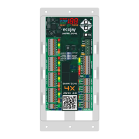
I88
HI TEMP
LO TEMP
SUPPLY
PURGEDELAY ECO
ecojay
SmartZone
FRESH AIR
4X
SmartZone
ZS4X
2.0
SmartZone
- 2.0 -
Use the ECOJAY
SmartZone
Controller to operate
dampers, equipment
and thermostat calls.
MEASURE the actual CFM provided by the Fresh Air Damper using
an anemometer to make the „Fresh Air Run Time‟ calculation.
Set this time
on the SmartZone-4X using the steps above.
= 60 min X
CFM-Needed
Measured-CFM
„Fresh Air
Run Time‟
6” 30-50
7” 50-80
8” 80-120
9” 120-170
10” 170-230
Round Size CFM
CFM-Needed
PRESS ‘STAT TYPE’
(4 times)
TO GET TO ZONE 4
1
I
HI TEMP
LO TEMP
SUPPLY
PURGEDELAY ECO
ONE
TIME...
2
HI TEMP
LO TEMP
SUPPLY
PURGEDELAY ECO
TWO
TIMES...
3
HI TEMP
LO TEMP
SUPPLY
PURGEDELAY ECO
THREE
TIMES...
4
HI TEMP
LO TEMP
SUPPLY
PURGEDELAY ECO
FOUR
TIMES
FA
HI TEMP
LO TEMP
SUPPLY
PURGEDELAY ECO
TO SELECT „FA‟
PRESS ▲
PRESS ‘STAT TYPE’
TO SET # MINUTES PER HOUR
“FRESH AIR RUN TIME”
USE ▲▼TO SET IN 5 MIN INCREMENTS
(SET FROM 0 TO 60 MINUTES)
2
3
0
HI TEMP
LO TEMP
SUPPLY
PURGEDELAY ECO
60
HI TEMP
LO TEMP
SUPPLY
PURGEDELAY ECO
5
HI TEMP
LO TEMP
SUPPLY
PURGEDELAY ECO
FRESH AIR Setup & Configuration
BUILT IN TO SMARTZONE-4X WILL AUTOMATICALLY
ENERGIZE FAN AND OPEN FRESH AIR DAMPER (ZONE 4)
DURING „FRESH AIR RUN TIME‟
FRESH AIR CONTROL
►FRESH AIR CAN BE CONFIGURED USING THE PUSHBUTTONS
►UTILIZES THE EQUIPMENT „FAN‟ TERMINAL
► CONTROLS A FRESH AIR DAMPER WITH THE ZONE 4 TERMINAL
USE THE CALCULATION BELOW TO SET THE # OF MINUTES „FRESH
AIR RUN TIME‟ TO SATISFY THE ASHRAE 62.2 REQUIREMENTS.
WHEN ZONE 4 IS CONFIGURED AS FRESH AIR, THE ZONE 4 THERMOSTAT INPUTS
CAN BE USED FOR MORE GRANULAR CONTROL OF THE FRESH AIR RUN TIME(S).
BY MAKING A CONNECTION BETWEEN “R” AND “Y, G, W, OR O/B” THE FRESH AIR
RUN TIME CAN BE AFFECTED AS FOLLOWS:
►Y = RUNS ONLY DURING COOLING
►G = FRESH AIR ON (DEMAND)
►W = RUNS ONLY DURING HEATING
►O/B = FRESH AIR OFF (DISABLE)
ADVANCED Fresh Air
BY CONNECTING R TO G VIA
A SIMPLE SWITCH, THE
USER CAN DEMAND „FRESH
AIR RUN TIME‟ EASILY.
FRESH AIR ON-OFF SWITCH
Floor
Area
BEDROOMS
0-1 2-3 4-5 6-7 >7
< 1500 30 45 60 75 90
1501 - 3000 45 60 75 90 105
3001 - 4500 60 75 90 105 120
4501- 6000 75 90 105 120 135
6001 - 7500 90 105 120 135 150
>7500 105 120 135 150 165
For the purpose of Fresh Air
Damper size selection, this
chart shows approximate
CFM each size is capable of.
ASHRAE 62.2 Fresh Air
SELECT THE
CFM-NEEDED
FROM THE CHART
ON THE RIGHT
AND PLUG IT
INTO THE
FORMULA
BELOW.
8
POWER
24V
24C
DAMPER
2
Z2-PC
COM
DAMPER
3
Z3-PO
Z3-PC
COM
DAMPER
4
Z4-PO
Z4-PC
COM
ZONE
4
STAT or FA
R
C
Y
G
O/B
W
FRESH AIR
SmartZone-4X – 2.0
9
CLOSE THIS CIRCUIT
WITH ANY SWITCH
(TIMER, SENSOR, ETC)
TO BRING ON
FRESH AIR
Outside Air
PO
PC
COM
Static Pressure
Controller (SPC)
PITOT TUBE
 Loading...