3.2 EMP III E60 and EMP IV E60
1
2
3
4
4
5
5
6
7
8
9
10
11
11
12
12
A
A
1
2
5
3
11
12
4
11
12
4
5
10
6
7
8
9
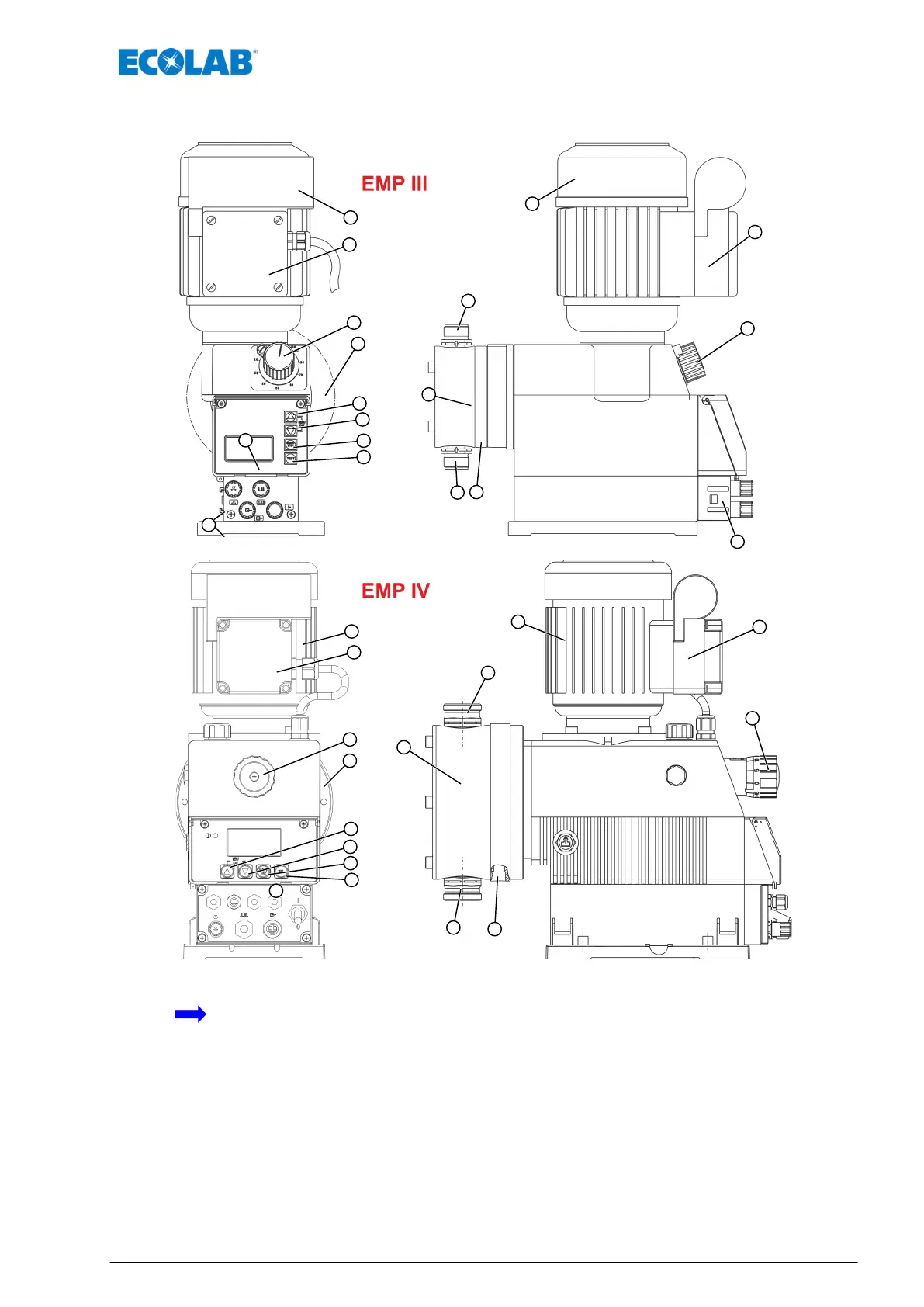
Fig. 3: Structure EMP III E60 and EMP IV E60
Flow direction of the metering medium
1 Diaphragm breakage sequence
2 Suction valve
3 Pressure valve
4 Control knob for setting the stroke length
5 Pump head
6 Menu/Exit, up arrow Button
7 Menu/Exit, down arrow Button
8 Start/Stop key (Enter function)
9 Test key
10 Graphical display
11 Engine (EMP III and EMP IV only)
12 Terminal box (only with EMP III and EMP IV)
A Rail for connecting the dongle box
Setup
9 MAN033535 Rev. 06-04.2020
 Loading...