Do you have a question about the Econar GeoSource PumpPAK GPP 1S25-1-A and is the answer not in the manual?
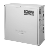
The ECONAR GeoSource PumpPAK™ is a crucial component in closed-loop geothermal heat pump systems, designed to efficiently circulate earth loop fluid. This system is a product of ECONAR Energy Systems, Corp., a company with over fifteen years of experience in producing geothermal heat pumps, particularly for cold winter climates like Minnesota. The design philosophy behind ECONAR's equipment, including the PumpPAK™, focuses on maximizing energy savings in heating-dominated regions without compromising comfort. Beyond heating, the system also provides efficient cooling, dehumidification, and optional domestic hot water heating, all integrated into a single, neatly packaged unit.
Geothermal heat pumps, as the name suggests, operate by transferring heat to and from the earth. The earth-coupled heat exchanger, or geothermal loop, serves as the primary source for heating and the absorption point for discharged energy during cooling. The system utilizes a compression cycle, similar to a refrigerator, to collect the earth's energy and use it to heat a home. Since this process involves moving existing energy rather than creating it, the efficiencies achieved are significantly higher—three to four times greater than even the most efficient fossil fuel systems.
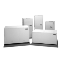
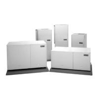
The GeoSource PumpPAK™ specifically addresses the need for effective fluid circulation within the earth loop in closed-loop heat pump applications. These units are available in four different sizes, designed to accommodate various residential and light commercial GeoSource 2000, Invision³, DualTEK, Ultra, Vara, or Vara 2 Plus heat pumps. For downflow heat pump models, the PumpPAK™ must be mounted remotely and connected using an accessory hose kit.
A key feature of the PumpPAK™ is its factory-plumbed and wired construction, which simplifies installation. To install the unit, users primarily need to mount it to the heat pump, connect the necessary wiring, attach the pipes from the earth loop, and then fill and purge the entire loop system. Safety and comfort are integral to ECONAR's design, with robust engineering and quality control ensuring excellent performance and customer satisfaction when properly applied and installed.
The PumpPAK™ units are available in four sizes, each utilizing one to four pumps. Correct sizing is critical and depends on several factors, including the heat pump size, the type and size of the earth loop, and the earth loop pressure drop. Users are advised to consult their local installer, distributor, or ECONAR's Customer Service for accurate sizing information.
Installation of the PumpPAK™ requires careful attention to safety warnings. Users must check the product ratings to ensure suitability for the application. It is crucial to read and follow all instructions and warnings, including labels, to prevent personal injury, death, or property damage. Electrical shock is a significant risk, so all power supplies must be disconnected before installing or servicing electrical devices. Only trained and qualified service personnel should perform installation, repair, or service.
An important note for installers is to mount and connect the PumpPAK™ before attaching the ductwork to the heat pump, as clearance can be minimal. For downflow models, remote mounting with an accessory hose kit is necessary. The PumpPAK™ assembly includes everything needed for mounting to the heat pump.
The installation process involves several steps:
System purging is a critical step to ensure proper heat pump operation. This involves filling and purging the closed-loop system to remove air. Each loop circuit requires sufficient water flow to achieve a two feet per second flow rate, typically needing a 1-1/2 to 3 HP high head pump to circulate fluid and direct air into a purging tank. The pump suction should draw from the bottom of a large container (purge cart), with a strainer on the suction line to prevent debris from re-entering the loop.
To purge the system:
For system startup, after the loop system is completely filled, purged, and pressurized, restore power to the unit and start the PumpPAK™ circulators to check for proper operation. If the circulators are not operating, turn off power and diagnose the problem. If operating correctly, measure the pressure drop across the heat pump using the P/T ports where the PumpPAK™ connects to the heat pump. Use the same pressure gauge for both readings for accuracy. Compare the measured pressure drop with data from the heat pump's Installation and Operating Instructions or ECONAR's Engineering Specifications manual. If the flow is too low, recheck PumpPAK™ sizing. If sizing is correct, trapped air or other restrictions in the earth loop may be the cause, requiring correction for proper heat pump operation.
The ECONAR GeoSource PumpPAK™ is designed for long-term reliability, backed by a comprehensive warranty. For residential applications, all parts are covered for two years, with labor costs covered during this period according to ECONAR's published Labor Rate Schedule. Refrigeration components are covered for five years, and heat exchangers carry a lifetime warranty for the original owner. For commercial applications, all parts are covered for one year, with labor costs covered during this period. Refrigeration components are covered for five years. The warranty begins on the date of original purchase, provided the warranty registration card is returned. If not, it starts from the date of manufacture based on the serial number. The warranty applies to the original installation and normal use of the heat pump and does not cover other system components. All ECONAR-labeled and manufactured accessories have a two-year part warranty for residential duty and a one-year part warranty for commercial duty, excluding labor. Service must be performed by an ECONAR authorized service person. Replacement parts are warranted for 90 days or for the remainder of the unit's warranty, whichever is longer. ECONAR is not liable for incidental or consequential expenses.
Owners are responsible for returning the warranty card, providing normal care and maintenance, and ensuring products are accessible for service. The warranty is void if the data label is defaced or removed, if the product has defects or damage due to alterations, improper electrical supply, shipping, handling, accidents, natural disasters, or other conditions beyond ECONAR's control. It is also void if products are not installed according to ECONAR instructions and specifications, or if defects/insufficient performance result from incorrect installations, poor water supply, design, improper application (including freeze rupture), or if products are installed or operated in a corrosive environment. The installing contractor provides warranty service; if unavailable, contact ECONAR Energy Systems, Corporation Customer Support.
| Model | GPP 1S25-1-A |
|---|---|
| Heating Capacity | 25, 000 BTU/h |
| Compressor Type | Scroll |
| Refrigerant | R-410A |
| Power Supply | 208/230V, 1 Phase, 60Hz |