AR2…SE.. Instructions 9 Form 120127
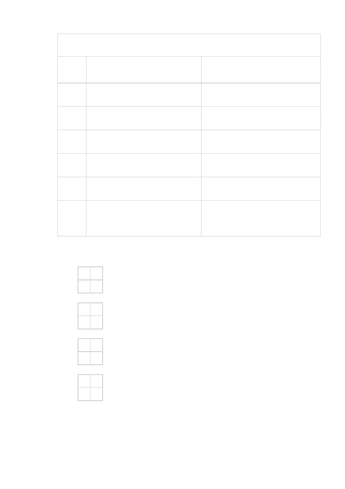
10.1 ELECTRONIC CONFIGURATION AR2…SE1 INPUT SIGNAL 0-10V OUTPUT SIGNAL 0-10V
DIP SWITCH POSITION
DIP
SWITCH
D
IP SWITCH ON LEFT
O
FF
D
IP SWITCH ON RIGHT
O
N
1
Clockwise Rotation
(from Power End side)
Counter-Clockwise Rotation
(from Power End side)
2
Low Resolution 125 steps High Resolution 200 steps
3
Standard setting (**) INPUT
and OUTPUT always aligned
4
Standard setting (**) INPUT
and OUTPUT always aligned
5
Input Signal 0-10 V d.c. N.A.
6
Impedance at 4400 Ohm
(only for Input Signal 0-10V).
Impedance at 250 Ohm
(only for Input Signal 0-10V).
** For other setting please look here below:
3
•
4
OFF
•
ON
STANDARD setting, Input and Output signal always aligned. Fo
example 2V input e 2V output.
3
•
4
OFF
•
ON
REVERSE OUTPUT (only for counter-clockwise rotation). Fo
example 2V Input signal and 8V Output Signal.
3
•
4
OFF
•
ON
DS-3 turned ON and DS-4 turned OFF. Actuator rotates for 90°
with Mid-Low Input Signal. For example 0-5V with rotation of 90°.
3
•
4
OFF
•
ON
DS-3 turned OFF and DS-4 turned ON. Actuator rotates for 90°
with Mid-High Input Signal. For example 5-10V with rotation of 90°.
 Loading...