19
Installing the Motherboard
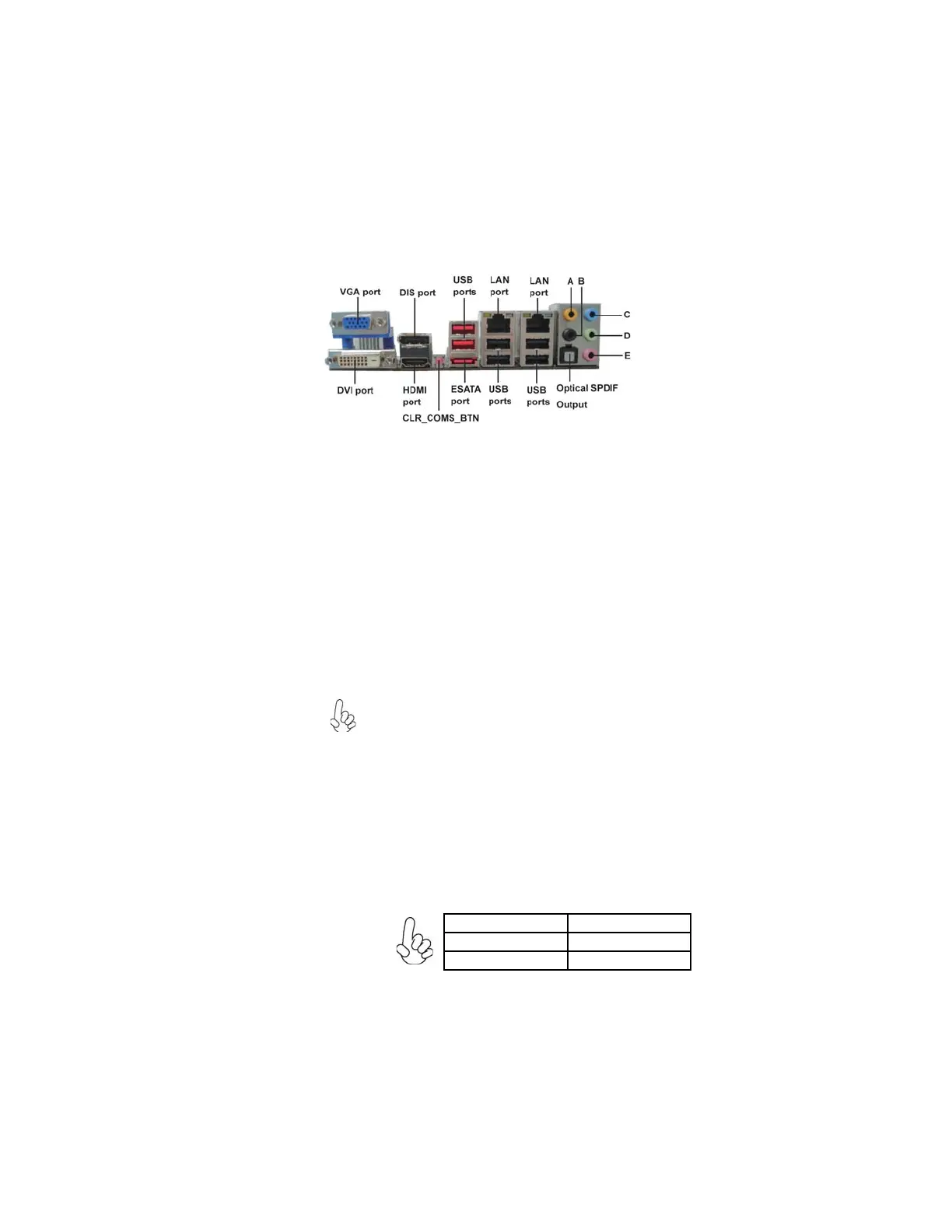
Connecting I/O Devices
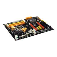
The backplane of the motherboard has the following I/O ports:
USB Ports Use the USB ports to connect USB devices.
LAN Port Connect an RJ-45 jack to the LAN port to connect your
computer to the network.
VGA Port Connect your monitor to the VGA port.
DVI Port Use the DVI port to connect the monitor.
ESATA Port
Use this port to connect to external SATA boxes or Serial
ATA port multipliers.
Before connecting the eSATA cables, make sure to turn off
the power of the external enclosure.
DIS Port(Dispaly
Port)
CLR_COMS_BTN Use the CLR_CMOS button to clear CMOS.
Audio Ports Use the audio jacks to connect audio devices. The C port is
for stereo line-in signal, while the E port is for microphone
in signal. This motherboard supports audio devices that cor-
respond to the A, B and D port respectively. In addition, all
of the 3 ports, B, and D provide users with both right & left
channels individually. Users please refer to the following
note for specific port function definition.
This jack connects to external optical digital audio output
devices.
Optical SPDIF
Output
The above port definition can be changed to audio input or
audio output by changing the driver utility setting.
A: Center & Woofer D: Front Out
B: Back Surround E: Mic_in Rear
C: Line-in -
Use the Display port to connect the monitor.
HDMI Port Connect the HDMI port to the HDMI devices.
 Loading...