35
Step 1: Contact an ECS Engineer to determine a location within the sprinkler system where corrosion
is likely to occur. In wet pipe systems locate on a high point at the air/water interface; in dry
pipe and preaction systems locate on a horizontal portion of the mains in an area with trapped
water.
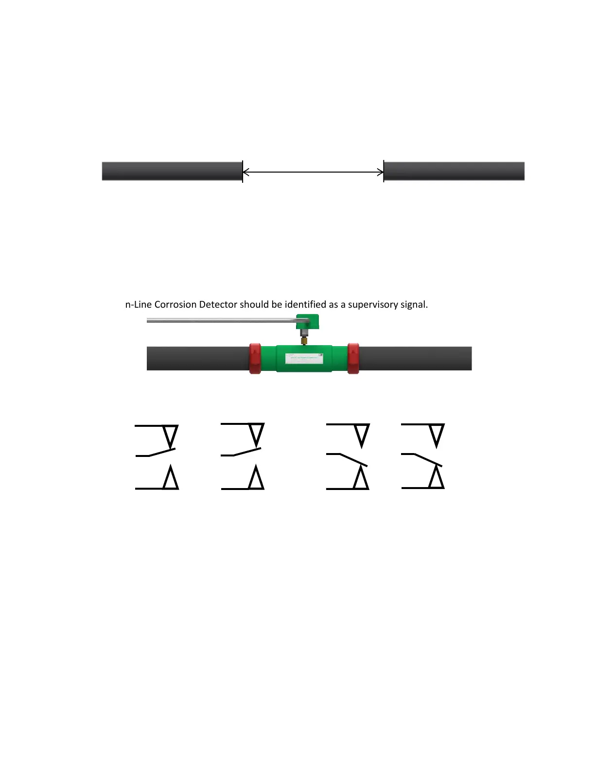
Step 2: At the chosen location in the fire sprinkler piping remove an eighteen (18) inch pipe section
from the fire sprinkler system.
Step 3: Roll groove the remaining ends of the fire sprinkler system piping to receive a standard
mechanical coupling.
Step 4: Install the In-Line Corrosion Detector of matching pipe material, diameter and schedule into
the section space that has been created with the removal of the eighteen (18) inch pipe
section. Orient the In-Line Corrosion Detector so that the pressure switch is accessible for
maintenance. Tighten the mechanical couplings as per the manufacturer’s specifications.
Step 5: OPTIONAL: Connect the wiring from the monitoring system to the pressure switch
(dry contact) in accordance with the manufacturer’s wiring instructions. Activation of the
In-Line Corrosion Detector should be identified as a supervisory signal.
Model EPS10-2 Pressure Switch Electrical Connections
Response to Device Activation
Activation of the pressure switch indicates that the thin wall section of the device has failed and the
pressure chamber is exposed to system pressure. Contact ECS for instructions regarding replacement and
testing of the failed In-Line Corrosion Detector.
 Loading...