23
Installing the Motherboard
F_USB1~2: Front Panel USB headers
The motherboard has four USB ports installed on the rear edge I/O port array.
Additionally, some computer cases have USB ports at the front of the case. If you
have this kind of case, use auxiliary USB connector to connect the front-mounted
ports to the motherboard.
IRDA: Infrared port (Optional)
The motherboard supports an Infrared (IRDA) data port. Infrared ports allow the
wireless exchange of information between your computer and similarly equipped
devices such as printers, laptops, Personal Digital Assistants (PDAs), and other
computers.
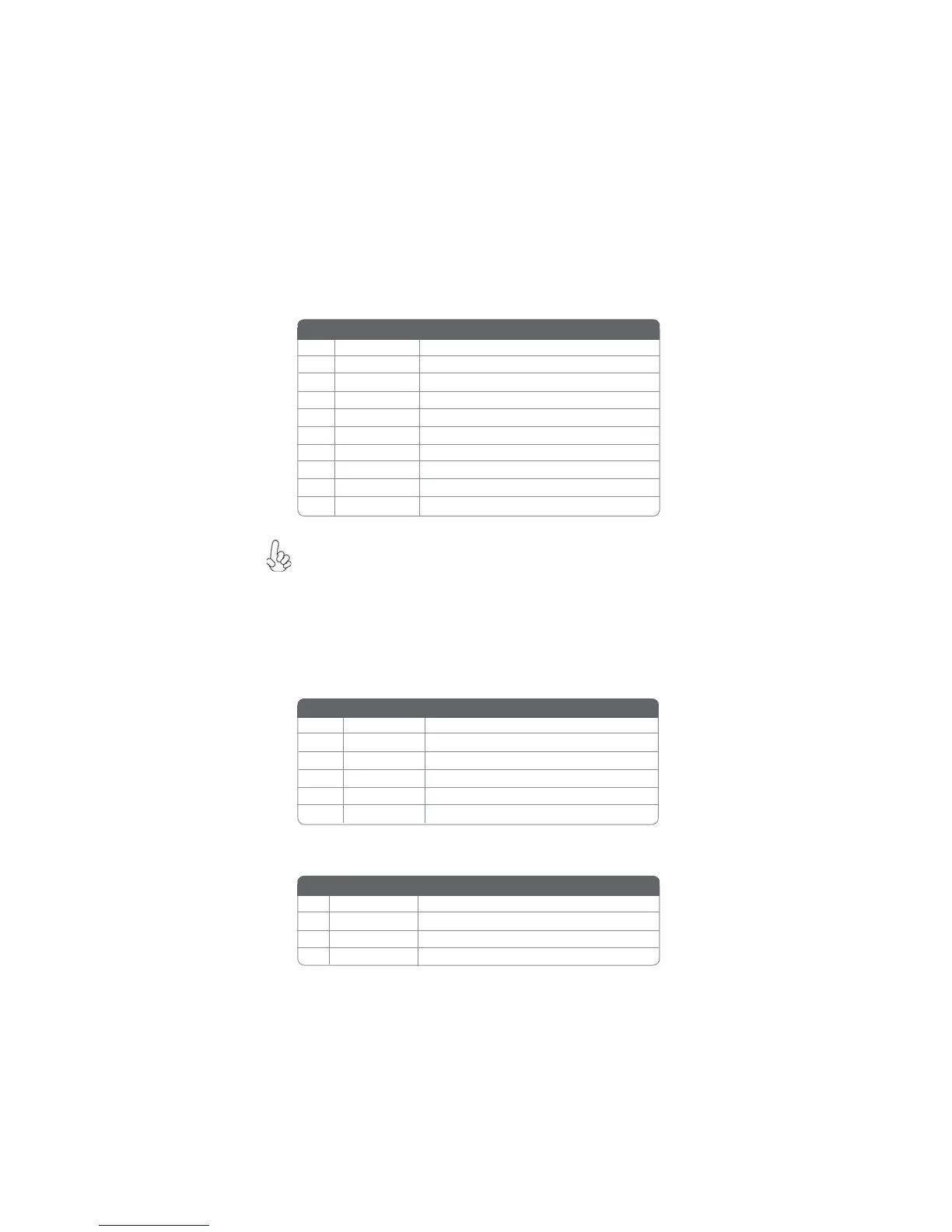
1 USBPWR Front Panel USB Power
2 USBPWR Front Panel USB Power
3 USB_FP_P0- USB Port 0 Negative Signal
4 USB_FP_P1- USB Port 1 Negative Signal
5 USB_FP_P0+ USB Port 0 Positive Signal
6 USB_FP_P1+ USB Port 1 Positive Signal
7 GND Ground
8 GND Ground
9 Key No pin
10 NC Not connected
Function
Pin Signal Name
Please make sure that the USB cable has the same pin assignment as
indicated above. A different pin assignment may cause damage or system
hang-up.
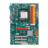
Pin Signal Name Function
1 Not assigned Not assigned
2 KEY No pin
3 +5V IR Power
4 GND Ground
5 IRTX IrDA serial output
6 IRRX IrDA serial input
Function
Pin Signal Name
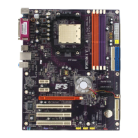
CD_IN: Analog Audio Input header
1 CD_Right CD In right channel
2 CD_GND Ground
3 CD_GND Ground
4 CD _Left CD In left channel
Function
Pin Signal Name