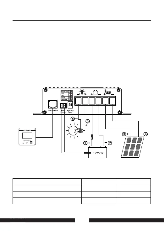
The connection plans show the maximum terminal assignment for
operation of all existing functions of the solar controller. The minimum
terminal assignment consists of the solar panel inputs (“+” and “-”) and the
connections to the main battery.
Connection Plan
SC 20 MPPT & SC 40 MPPT
Required Cable Cross-Sections SC 20 SC 40
+/-PanelCables,lengthasrequired
4-6mm
2
6-10mm
2
+/-BatteryIcables,lengthmax.2m
4-6mm
2
6-10mm
2
FuseclosetoBatteryI(CableProtection)
35A 60A
27
Note:
InstallMPPTsolar
chargecontroller
neartheMain
battery!
Fuse
30A
Temperature
Sensor
12V:max.240W
24V:max.480W
SolarMonitor
(optional)