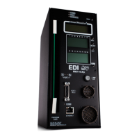
MMU2-16LE Series SmartMonitor
®
Malfunction Management Unit
Operations Manual
Eberle Design Inc. Page 5
to the unit between the MMU input and AC NEUTRAL (See Sections 5.5.3.9 and 6.2.4
of NEMA Standards Publication TS2-2003 (R2008) v02.06).
1.4.1 LEDGUARD
®
LED FIELD SIGNAL SENSING
The Eberle Design MMU2-16LE SmartMonitor
®
can be configured to use a technique
called LEDguard
®
that is designed to better monitor the characteristics of LED based
signal loads (See Section 6.3.4.7). Each field signal input is measured and compared
to both a high threshold and a low threshold value to determine On / Off status. This
differs from conventional standard NEMA operation where the active threshold is
picked according to the color of the field signal. Once the high and low On / Off
thresholds (Section 8.1.2) have been determined using the input RMS voltage, the
individual fault monitor functions use the appropriate threshold to determine if a fault
condition exists.
1.4.2 TYPE SELECT INPUT
The MMU2-16LE SmartMonitor
®
will operate as a Type 16 monitor with sixteen
channels when the TYPE SELECT input is a logic True (low). The MMU2-16LE
SmartMonitor
®
will operate as a Type 12 monitor with twelve channels when the TYPE
SELECT input is a logic False (high) or open circuit.
Type 16 - Each channel has three inputs: RED (DON’T WALK), YELLOW, and
GREEN (WALK).
Type 12 - Each channel has four inputs: RED, YELLOW, GREEN, and WALK.
The MMU2-16LE SmartMonitor
®
is normally configured as a 16 channel (Type 16)
monitor when operated in a TS2 type cabinet assembly. The Type 12 mode is intended
to provide downward compatibility with 12 channel Conflict Monitor Units (CMU)
conforming to NEMA Traffic Control Systems Publication TS1-1989. When operating in
the Type 12 mode, the MMU2-16LE SmartMonitor
®
monitoring functions are the same
as the Type 16 mode except that Port 1 communications are disabled and Field Check
Monitoring is disabled. See also TYPE 12 MODE WITH SDLC Option, section 1.4.2.1.
1.4.2.1 TYPE 12 WITH SDLC MODE
The MMU2-16LE SmartMonitor
®
can operate in a NEMA TS-1 configured cabinet with
the full advantages of the Port 1 SDLC communications to the Controller Unit including
Field Check monitoring. In this mode the MMU2-16LE SmartMonitor
®
channel displays
operate in the Type 12 configuration displaying the Walk input status directly on the
associated vehicle channels (2, 4, 6, and 8). Certain requirements exist for this mode to
operate correctly:
1. This mode is limited to a maximum of four Ped phases which must be
assigned to vehicle phases 2, 4, 6, and 8. The Walk field terminals must be
wired to the MMU2-16LE SmartMonitor
®
channel inputs 2W, 4W, 6W, and
8W on MMU connector pins MSA-y, MSA-FF, MSA-EE, and MSA-u
respectively. This is conventional wiring for a standard NEMA TS-1 cabinet.
MMU input TYPE SELECT (pin #HH) must be “open circuit” (False).
2. The Controller Unit (CU) must be TS-2 Type 2 capable and provide the Port
1 EIA-485 communications port. The Controller Unit must be configured for

 Loading...