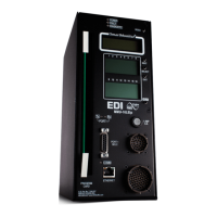
MMU2-16LE Series SmartMonitor
®
Malfunction Management Unit
Operations Manual
Eberle Design Inc. Page 2
From start to finish, a technician can use the Set-up Wizard to accurately and quickly
configure the monitor, and then use the Diagnostic Wizard to analyze the cause of a
malfunction without the need for understanding complex monitor terminology and
theory.
1.2.3.1 SET-UP WIZARD
The built-in Set-up Wizard (see Section 6.3.14) configures the monitor enhanced-
feature programming using a simple series of intersection related questions. It allows a
technician to accurately and completely program the MMU2-16LE SmartMonitor
®
enhanced functions without the need for understanding the complexities of monitor
enhanced configuration parameters.
1.2.3.2 DIAGNOSTIC WIZARD
The built-in Diagnostic Wizard (see Section 3.10) is an integral part of the Help System
that provides detailed diagnostic information regarding the fault being analyzed. The
Wizard provides a concise view of the signal states involved in the fault, pinpoints faulty
signal inputs, and provides guidance on how the technician should isolate the cause of
the malfunction.
1.2.4 PROGRAM CARD MEMORY
All monitor enhanced-feature programming is stored in a nonvolatile memory contained
on the EDI Program Card. When replacing the MMU2-16LE SmartMonitor
®
for service
or test purposes, all NEMA standard and enhanced-feature programming is
automatically transferred to the replacement unit when the EDI Program Card is
inserted. The EDI Program Card is completely compatible with other MMU models
compliant with the NEMA TS-2 Standard.
The Program Card Memory function must be enabled before use. The factory
default setting is Off. See Section 6.3.4.6.
1.2.4.1 MMU2 PROGRAM CARD MEMORY BACKWARD COMPATIBILITY
All configuration settings are compatible between previous legacy versions of the
MMU-16LE SmartMonitor
®
firmware except for the Flashing Yellow Arrow parameters.
When a Program Card configured with legacy FYA settings Enabled is installed into
this unit, the resulting FYA settings will be set according to the table below, but only if
the NEMA MMU2 FYA settings were not already enabled.
To emulate the legacy settings the following translation should be used:
Legacy FYA Mode
1.2.5 RMS VOLTAGE REPORTING
Input voltages are measured using a true Root Mean Squared (RMS) technique. A
dedicated Digital Signal Processor (DSP) RMS-Engine controls the analog to digital
(A/D) hardware which samples each AC input voltage a minimum of 32 times per cycle.
The RMS-Engine then calculates the true RMS voltage value producing accurate
results which are very insensitive to changes in frequency, phase, wave shape, and
distortion.
1.2.6 ECCOM SOFTWARE INTERFACE
The field proven EDI ECcom Signal Monitor Communications software provides a
laptop computer or system interface to all information contained in the monitor. This
 Loading...