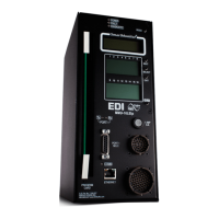
MMU2-16LE Series SmartMonitor
®
Malfunction Management Unit
Operations Manual
Eberle Design Inc. Page 41
For applications using Flashing Yellow Arrow (FYA), the FYA parameters should be
configured first before running the Set-up Wizard.
6.4.1 UNUSED CHANNELS
This step selects the channels of the MMU2-16LE SmartMonitor
®
that are not
connected to a load switch, that is, unused. This selection can eliminate the need to
connect the Red input of an unused channel to AC+. The NEXT button moves the ▼
symbol to the next channel number. The SELECT button will toggle from the OTHER
state to the UNUSED state. A channel that is selected for UNUSED is indicated by the
and and icons illuminated.
Designating a channel as UNUSED does not affect the Conflict programming on the
Program Card.
When all UNUSED channels have been selected, the EXIT button will display the
navigation choices of NEXT, CANCEL, and EDIT. The NEXT choice continues the
Wizard operation with the next programming step. The CANCEL choice will exit from
the Wizard operation with no changes to the configuration data base. The EDIT choice
will return to the Unused Channels step.
6.4.2 PEDESTRIAN CHANNELS
This step selects the channels of the MMU2-16LE SmartMonitor
®
that are connected to
a pedestrian load switch that drives the Walk and Don’t Walk signal display. In NEMA
TS-2 Type 16 mode, the Wizard will ask if the Don’t Walk signal is to be monitored.
Answering YES will configure the MMU2-16LE SmartMonitor
®
to respond to a Red Fail
or Dual Indication (R+G) fault if the Don’t Walk signal fails.
In NEMA TS-1 Type 12 operation, this step is not required as the Walk input is
programmed to the associated vehicle monitor channel (R, Y, G, W).
The NEXT button moves the ▼ symbol to the next channel number. The SELECT
button will toggle from the OTHER state to the PED state. A channel that is selected for
PED is indicated by the (and ) icons illuminated.
When all PED channels have been selected, the EXIT button will display the navigation
choices of NEXT, CANCEL, and EDIT. The NEXT choice continues the Wizard
operation with the next programming step. The CANCEL choice will exit from the
Wizard operation with no changes to the configuration data base. The EDIT choice will
return to the Pedestrian Channels step.
6.4.3 PROTECTED-PERMISSIVE TURN CHANNELS
This step selects the channels of the MMU2-16LE SmartMonitor
®
that are connected to
a protected-permissive left turn channel load switch that drives only a Green and
Yellow signal display. This selection can eliminate the need to connect the Red input of
a protected-permissive turn channel to AC+. This selection can also include a right turn
overlap that drives only a Green and Yellow signal display. The NEXT button moves
the ▼ symbol to the next channel number. The SELECT button will toggle from the
OTHER state to the PP-TURN state. A channel that is selected for PP-TURN is
indicated by the and icons illuminated.
When all PP-TURN channels have been selected, the EXIT button will display the
navigation choices of NEXT, CANCEL, and EDIT. The NEXT choice continues the
Wizard operation with the next programming step. The CANCEL choice will exit from
the Wizard operation with no changes to the configuration data base. The EDIT choice
will return to the Protected-Permissive Turn Channels step.

 Loading...