4
The GP-101ET is installed between the PSE (Power Source Equipment) and the
PD (Powered Device); it is powered by PSE and forwards the Ethernet data
and remaining PoE power to the PD. The GP-ET does’t euie a
external power supply and it can be installed easily just plug and play; The
GP-101ET injects power to the PDs without affecting the data transmission
performance. It offers a cost effective and quick solution to extend power and
data an additional 100m.
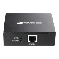
Connect GP-101ET to the Power Source Equipment (PSE)
Step 1: Connect a standard Cat.5/5e/6 UTP cable from Power Source
Equipment (PSE), such as PoE Switch, PoE Injector hub and single port PoE
ijeto, to the IN pot of GP-101ET.
Step 2: The PSE delivers both Ethernet Data and PoE power over UTP cable to
the GP-ET ad the PoE IN LED ill e steady on.
Connect Gp-101ET to the Powered Device (PD)
Setp 1: Connect the additional Cat.5/5e/6 cable that will be used to connect to the
eote Poeed Deie PD to the OUT pot of GP-101ET.
Setp 2: The "OUT" port is also the power injectors which transmit DC Voltage to the
Cat.5/5e/6 cable and transfer data and power simultaneously between the PSE and
PD.
Setp 3: Once GP-101ET detects the existence of an IEEE 802.3at / 802.3af device,
the PoE OUT LED idiato ill e steady, ON to shos it is poiding power.