This document outlines the assembly and detailing instructions for the Eduard FE 1142 Bf 109G-6/AS Weekend photo-etched parts set, designed to enhance a 1/48 scale model of the Messerschmitt Bf 109G-6/AS aircraft. The set provides intricate details for various sections of the model, including the cockpit, fuselage, and external components, aiming to achieve a higher level of realism compared to the base plastic kit.
Function Description
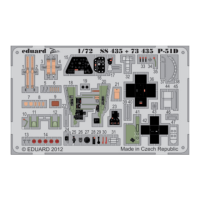
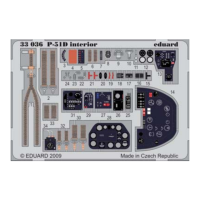
The Eduard FE 1142 photo-etched set serves to upgrade and detail a 1/48 scale model of the Bf 109G-6/AS. Photo-etched parts are thin metal components, typically made of brass, that are chemically etched to create fine details that are difficult or impossible to replicate with injection-molded plastic. These parts are used to replace or augment existing plastic parts, adding depth, texture, and accuracy to the model. The set primarily focuses on the cockpit interior, providing instrument panels, control surfaces, seatbelts, and other small fixtures. It also includes details for the fuselage, such as vents, access panels, and structural elements, as well as external enhancements like landing gear components and canopy frames. The overall function is to elevate the model's appearance to a "museum quality" standard, appealing to experienced modelers seeking a high level of detail.
Important Technical Specifications
Scale: 1/48, indicating that the model is 1/48th the size of the actual aircraft.
Material: Photo-etched brass (or similar metal alloy). This material allows for very thin and precise parts, crucial for scale accuracy.
Compatibility: Specifically designed for the Bf 109G-6/AS Weekend edition kit. While some parts might be adaptable to other Bf 109G-6 kits, optimal fit and accuracy are guaranteed with the specified kit.
Part Count: The set includes multiple sheets of photo-etched parts, identified by codes like FE 1142. The instructions detail the use of specific parts, such as H3, H32, H33, H34, H36, H50, AC1, AC5, AC6, AC17, I2, I3, I9, I10, I11, I12, I13, I14, I15, I16, I17, I18, I19, I20, I22, I23, I24, I25, I28, I29, I30, I31, I32, I33, I34, I35, I36, I37, I38, I39, I40, I41, I42, I43, I74, U2, U3, U4, and others. Each part is meticulously numbered for easy identification during assembly.
Dimensions: The instructions specify certain dimensions for modifications, such as drilling holes with a diameter (Ø) of 0.5 mm or 0.2 mm, and cutting plastic parts to a length (L) of 0.5 mm. These precise measurements are critical for proper fit and appearance.
Coloration: Some photo-etched parts are pre-painted (indicated by "COLOR" or "PAINTED" in the instructions), typically for instrument panels and cockpit details, to save the modeler time and achieve accurate colors. Other parts require painting by the modeler.
Usage Features
Assembly Process:
The assembly process involves several key steps:
- Preparation of Original Kit Parts: Many original plastic kit parts need to be modified, which includes cutting, sanding, or removing specific sections. This is indicated by red lines and "REMOVE" instructions in the diagrams. For example, in the cockpit assembly, parts of the instrument panel and side consoles are removed to accommodate the photo-etched replacements.
- Bending Photo-Etched Parts: Photo-etched parts are flat and often need to be bent into three-dimensional shapes. This is indicated by arrows and "BEND" instructions. Specialized tools like photo-etch bending pliers are highly recommended for precise bends.
- Adhesion: Photo-etched parts are typically attached using cyanoacrylate (CA) glue (super glue) or epoxy. The instructions do not explicitly state the adhesive type but imply the use of a strong, fast-drying adhesive suitable for metal-to-plastic bonding.
- Layering: Many cockpit details involve layering multiple photo-etched parts to create a multi-dimensional effect, such as instrument panels with clear film for gauges.
- Painting: While some parts are pre-painted, others require painting to match the aircraft's interior or exterior colors. The instructions provide general guidance on which parts are colored.
- Symmetrical Assembly: For parts that need to be assembled symmetrically, the instructions explicitly state "SYMETRICAL ASSEMBLY," ensuring balanced placement.
- "DO NOT USE" Parts: The instructions clearly mark parts from the original kit that are not to be used with the photo-etched set, often because they are replaced by the metal parts.
- "FILL" Parts: Some original kit parts may need to have holes or gaps filled, indicated by "FILL" instructions, to ensure a smooth surface for the photo-etched details.
- "ONLY" Instructions: Specific parts are designated for use "with kit part I2 only" or "with kit part I3 only," highlighting conditional usage based on the base kit's components.
Specific Assembly Examples:
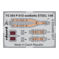
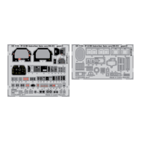
- Cockpit (Page 1): This section is highly detailed. Original kit parts are extensively modified. Photo-etched parts H3, H32, H33, H34, H36, H50, and others are used to create the instrument panel, side consoles, rudder pedals, and seatbelts. The instructions show how to layer parts to create realistic gauges and switches. Parts are bent and attached to form the complex shapes of the cockpit interior.
- Fuselage Interior (Page 2): Parts AC1, AC5, AC6, AC17, H3, H32, H33, H35, and others are used to detail the internal structure of the fuselage, including bulkheads, radio equipment, and access panels. This section often involves removing plastic details and replacing them with finer photo-etched versions.
- External Fuselage and Wings (Page 3): This section focuses on external details such as vents, flaps, and access panels. Parts I28, I29, I30, I31, I32, I33, I34, I35, I36, I37, I38, I40, I74, and others are used. Some instructions involve drilling holes (e.g., Ø 0.5mm) to insert new photo-etched parts or to create mounting points. The instructions also show how to modify the wing flaps and radiators.
- Canopy and Landing Gear (Page 4): Details for the canopy frame, landing gear components, and other small external features are provided. Parts I18, I25, I39, I41, I42, U2, U3, U4, and others are used. The instructions differentiate between "open canopy" and closed canopy configurations, providing specific parts for each. For example, part I41 is used for the open canopy, while I42 is for the closed canopy.
Tools Recommended:
- Hobby knife or sharp blade for cutting plastic.
- Fine-grit sandpaper or sanding sticks for smoothing plastic.
- Photo-etch bending tool (e.g., Hold and Fold) for precise bends.
- Fine-tipped tweezers for handling small parts.
- Cyanoacrylate (CA) glue (super glue) with a fine applicator.
- Small drill bits (0.2mm, 0.5mm) and a pin vise.
- Magnifying lamp or visor for working with tiny parts.
Maintenance Features
This product is a static model enhancement, so "maintenance" in the traditional sense does not apply. However, there are considerations for handling and storage:
- Handling: Due to the delicate nature of photo-etched parts, especially after assembly, the finished model should be handled with extreme care to prevent bending or breaking the fine details.
- Cleaning: The finished model can be gently dusted with a soft brush or air blower. Avoid harsh chemicals or excessive moisture, which could damage paint or adhesive.
- Storage: Store the model in a dust-free environment, preferably in a display case, to protect it from physical damage and environmental factors.
- Unused Parts: Any unused photo-etched parts should be kept in their original packaging or a secure container to prevent loss or damage, as they might be useful for future projects or repairs.
In summary, the Eduard FE 1142 Bf 109G-6/AS Weekend photo-etched set is a comprehensive detailing kit that significantly enhances the realism and visual appeal of a 1/48 scale model. Its successful application requires careful attention to the detailed instructions, precise execution of cutting and bending, and the use of appropriate modeling tools and adhesives. The result is a highly detailed and accurate representation of the Bf 109G-6/AS cockpit and other key areas.