EasyManua.ls Logo

Edwards AB4G - User Manual

Edwards AB4G
6 pages
Print Icon
To Next Page IconTo Next Page
Loading...
© 2014 UTC Fire & Security Americas Corporation, Inc. 1 / 6 P/N 3100672-EN • REV 07 • ISS 23JAN14
AB4G Audible Detector Base Installation Sheet
Description
This installation sheet applies to AB4G Audible Detector Base
units with model numbers GSA-AB4G and SIGA-AB4G.
The AB4G Audible Detector Base adds an audible output
function to any Signature Series detector. The output of this
detector base is field-configurable for output tone (steady or
temporal) and output volume (low or high dBA).
Depending on the system supporting the Signature loop, the
base can:
Follow the state of the device it supports
Be configured (in the SDU) for other operating modes
Be controlled by program rules
The base uses the same address and programming label as
the detector it supports.
Installation
Install this device in accordance with applicable national and
local codes, ordinances, and regulations.
Cautions
To avoid accidental damage to the panel, disconnect all
power before wiring the unit.
Do not loop the signaling circuit field wires around the
terminals.
Note: Always connect the base to a continuous voltage,
whether the output tone on the audible detector base is set to
steady or temporal.
Sleeping rooms: In sleeping areas, use the high dBA output
and temporal tone settings.
AB4G-SB: When using the AB4G-SB box, install a reinforcing
plate at every knockout. (Reinforcing plates are included with
the box.) Remove the knockout first and then slide the
reinforcing plate into the plastic housing. After the plate is in
place, install the conduit connector and nut. See Figure 1.
Typically, the base is configured to produce a high dBA
temporal tone and is connected to a notification appliance
circuit that outputs a continuous 24 VDC signal.
Refer to Figure 2 when following the installation steps given
below.
To install the audible detector base:
1. The unit default is for high dBA output. To set the output to
low dBA, cut the circuit board trace as marked on the back
of the PC board. See Figure 3.
2. The unit default is for temporal pattern output. To set the
output to steady tone, cut the circuit board trace as
marked on the back of the PC board. See Figure 3.
3. Select and install a compatible electrical box, and then
bring the field wiring into the box.
4. Connect the field wiring to the terminals on the back of the
base plate. For the unit to function properly, observe
polarity. See Figure 3.
5. Attach the base plate to the electrical box.
6. Align the trim ring so that the four tabs on the ring mate
with the four slots in the base plate, and then press the
trim ring onto the base plate until the tabs lock.
7. Attach the desired Signature detector to the base. Align
the arrows on the detector and trim ring, press the
detector into the base, and then rotate the detector until it
locks into place.
8. Apply power and activate the unit to verify that it is
operating properly.
Question and Answer IconNeed help?

Do you have a question about the Edwards AB4G and is the answer not in the manual?

Summary

Description

Installation

Wiring diagram

Maintenance

Specifications

Regulatory information

Applications

Local alarm signaling application

Describes local alarm signaling scenarios and the wiring required for the detector base.

Zone alarm signaling application

Details zone alarm signaling, activating bases in a notification zone via a CRR module.

Synchronized alarm signaling application

Explains synchronized alarm signaling using a G1M-RM for sound synchronization.

Overview

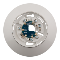
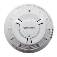
The AB4G Audible Detector Base, available in model numbers GSA-AB4G and SIGA-AB4G, is designed to add an audible output function to any Signature Series detector. This device enhances fire alarm systems by providing an audible alert directly at the detector base, making it suitable for various applications, including sleeping areas where high dBA output and temporal tone settings are recommended.

Function Description

The primary function of the AB4G Audible Detector Base is to provide an audible alarm in conjunction with a Signature Series detector. It integrates seamlessly with the Signature loop system, sharing the same address and programming label as the detector it supports. This means that when the associated detector senses smoke or heat, the base will activate its audible alarm.

The audible output of the detector base is highly configurable to meet specific installation and application requirements. Users can set the output tone to either a steady tone or a temporal (patterned) tone. Additionally, the output volume can be adjusted between low dBA and high dBA settings. These configurations are typically performed by cutting specific circuit board traces on the back of the PC board, as illustrated in the installation instructions. For instance, the unit defaults to high dBA output and temporal pattern output, but these can be changed by cutting the appropriate traces.

The base's operation is flexible and can be controlled in several ways:

  • Follow the state of the device it supports: The audible alarm will activate and deactivate in direct response to the alarm state of the attached Signature detector.
  • Configured (in the SDU) for other operating modes: The device can be programmed via the System Definition Utility (SDU) to operate in different modes, allowing for customized alarm behaviors.
  • Controlled by program rules: The audible output can be integrated into broader system programming rules, enabling complex alarm sequences or conditional activations based on other system events.

The AB4G Audible Detector Base is designed to be connected to a notification appliance circuit that typically outputs a continuous 24 VDC signal. This ensures a reliable power source for the audible function.

Usage Features

The AB4G Audible Detector Base is designed for straightforward installation and integration into existing fire alarm systems. It supports various electrical boxes, including the AB4G-SB surface box, 4-inch square boxes, 3-1/2 inch octagonal boxes, and standard European 100 mm² boxes. When using the AB4G-SB box, reinforcing plates are provided and must be installed at every knockout to ensure structural integrity.

Installation involves several key steps:

  1. Output Configuration: Before installation, the desired dBA output (high or low) and tone pattern (temporal or steady) are set by cutting specific traces on the circuit board. This allows for customization based on the environment, such as using high dBA and temporal tone in sleeping rooms.
  2. Electrical Box Installation: A compatible electrical box is selected and installed, with field wiring brought into the box.
  3. Wiring Connections: Field wiring is connected to the terminals on the back of the base plate. Proper polarity must be observed for the unit to function correctly. The wiring diagram specifies connections for AUX_RISER_IN, SLC_IN, AUX_RISER_OUT, and SLC_OUT, facilitating connection to the power supply, intelligent addressable controller, and subsequent devices or EOL relays.
  4. Base Plate and Trim Ring Attachment: The base plate is attached to the electrical box, followed by the trim ring, which aligns with slots on the base plate and locks into place.
  5. Detector Attachment: The Signature detector is then attached to the base. Arrows on the detector and trim ring guide alignment, and the detector is pressed into the base and rotated until it locks securely.
  6. Power Application and Verification: After installation, power is applied, and the unit is activated to verify proper operation.

The device supports various application scenarios:

  • Local Alarm Signaling: In this setup, an audible detector base activates only when its associated detector is triggered. Other bases on the same riser remain silent. The alarm continues until smoke clears and the control panel is reset.
  • Zone Alarm Signaling: This application uses a CRR (Control Relay Module) to activate all audible detector bases within a specific notification zone when any one detector in that zone activates. The alarm persists until smoke clears, the control panel is reset, the control panel's Auto Signal Silence timer expires, or it is silenced by the CRR (if programmed as a silencing relay).
  • Synchronized Alarm Signaling: For synchronized alarms, a CRR module activates all audible detector bases, and a G1M-RM module is used to synchronize the sound. This ensures that all audible alarms sound in unison. The alarm duration is similar to zone alarm signaling.

Maintenance Features

The AB4G Audible Detector Base is designed for minimal maintenance once installed. The primary maintenance consideration is to avoid altering the factory-applied finish, which helps preserve the device's integrity and appearance.

Key maintenance-related cautions and notes include:

  • Power Disconnection: To prevent accidental damage to the panel, all power must be disconnected before wiring the unit. This is a critical safety and device protection measure.
  • Wiring Practices: Field wires for the signaling circuit should not be looped around the terminals. This ensures proper electrical connections and prevents potential issues.
  • Continuous Voltage: The base must always be connected to a continuous voltage supply, regardless of whether the output tone is set to steady or temporal. This ensures that the device is always ready to activate its audible alarm when needed.

The robust design and clear installation guidelines contribute to the device's reliability and ease of long-term management within a fire alarm system. The ability to configure output settings during installation means that the device can be tailored to specific environmental needs, reducing the need for post-installation adjustments.

Edwards AB4G Specifications

General IconGeneral
Protection RatingIP65
Output TypeRelay
CategorySecurity Sensors
Voltage12-24V DC
Operating Voltage12-24V DC
Operating Temperature-20°C to +50°C
Beam ConfigurationQuad Beam
Current Consumption35 mA (standby), 45 mA (alarm)

Related product manuals