EasyManua.ls Logo

Edwards SIGA-IM

Edwards SIGA-IM
3 pages
To Next Page IconTo Next Page
Loading...
© 2019 United Technologies Corporation 1 / 3 P/N P-047550-1788-EN • REV 013 • ISS 08SEP19
SIGA-IM Isolator Module
Installation Sheet
Description
The SIGA-IM Isolator Module is an addressable device that protects a
signaling line circuit (SLC) from a wire-to-wire short. The SIGA-IM
module monitors line voltages and opens the SLC when a short is
detected, effectively isolating the short between the two isolator
modules located electrically closest to the short.
The SIGA-IM module requires one detector address on the SLC.
Addresses are assigned electronically. There are no address switches.
An LED provides visible indication of the status of the module:
Normal: Green LED flashes
Installation
Install this device in accordance with applicable national and local
codes, ordinances, and regulations.
NFPA 72 2013 – A single fault on a pathway connected to the
addressable devices shall not cause the loss of more than 50
addressable devices.
NFPA 72 2016 – A single fault on a pathway connected to the
addressable devices shall not cause the loss of the devices in
more than one zone.
Notes
The module is shipped from the factory as an assembled unit; it
contains no user-serviceable parts and should not be
disassembled.
This module does not operate without electrical power. As fires
frequently cause power interruption, discuss further safeguards
with your local fire protection specialist.
To install the module:
1. Write the address assigned to the module on the label provided,
and then apply the label to the module. Remove the serial number
label from the module, and then attach it to the project
documentation.
2. Wire the module as shown in Figure 2 on page 2.
3. Using the self-tapping screw provided, attach the wall plate to the
module. See Figure 1.
4. Using the four machine screws provided, attach the wall plate and
module to the electrical box.
Figure 1: Installation diagram
(1) Compatible electrical box
(2) SIGA-IM module
(3) Wall plate
(4) #6-32 × 5/8 machine screws (4X)
(5) #4 × 1/2 self-tapping screw
Wiring
Wire this device in accordance with applicable national and local
codes, ordinances, and regulations.
Notes
Refer to the Signature loop controller installation sheet for SLC
wiring specifications for additional details.
All wiring is power-limited and supervised.
To wire the module:
1. Verify that all field wiring is free of opens, shorts, and ground
faults.
2. Strip 1/4 in. (about 6 mm) from the ends of all wires that connect to
the terminal block of the module.
When stripping wire ends, exposing more wire may cause a
ground fault; exposing less wire may result in a faulty connection.
3. Make all wiring connections as shown in Figure 2.
Figure 2: Wiring diagram
(1)
(2)
(3)
(4)
(5)
SLC
SLC
SLC
SLC
Question and Answer IconNeed help?

Do you have a question about the Edwards SIGA-IM and is the answer not in the manual?

Edwards SIGA-IM Specifications

General IconGeneral
TypeIntelligent Input Module
Operating Temperature Range32°F to 120°F (0°C to 49°C)
Humidity10 to 93% RH, non-condensing
MountingSurface mount to a standard 4" square electrical box
Operating Voltage Range15-32 VDC

Summary

SIGA-IM Module Description

Module Functionality

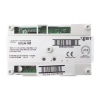
Explains the SIGA-IM module's role in protecting SLCs from shorts by monitoring voltage and opening the circuit.

LED Status Indicator

Describes the visible indication of the module's status via a green LED flashing.

SIGA-IM Module Installation Procedures

Installation Compliance

Instructions to install the device according to applicable national and local codes, ordinances, and regulations.

Installation Steps

Step-by-step guide for installing the module, including labeling and wiring preparation.

SIGA-IM Module Wiring Guide

Wiring Compliance and Preparation

Wire the device per codes, ensuring field wiring is free of faults and wires are properly stripped.

Wiring Connections

Instructions to make wiring connections as shown in the provided diagram.

SIGA-IM Module Application Scenarios

Class A Pathway Application

Describes segmenting SLCs in Class A pathways using SIGA-IM modules to prevent short circuits.

Class X Pathway Application

Details applying SIGA-IM modules in Class X pathways, including common enclosures and standard mount modules.

SIGA-IM Module Technical Specifications

Electrical Specifications

Details operating voltage, current (standby/alarm), resistance, and ground fault impedance.

Circuit and Wire Specifications

Covers circuit designation, signaling line circuit type, wire size, and compatible electrical boxes.

Environmental Specifications

Lists operating and storage temperature ranges, and relative humidity limits.

SIGA-IM Module Regulatory Compliance

FCC Compliance Statement

States compliance with FCC Rules, including conditions for operation and interference.

SIGA-IM Module Contact Information

Contacting Edwards Support

Provides information on where to find contact details for further assistance.

Related product manuals