2 / 6 P/N 3100672-EN • REV 07 • ISS 23JAN14
Figure 1: Installing reinforcing plates on the AB4G-SB box
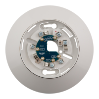
Figure 2: Installing the Audible Detector Base
Wiring diagram
Wire this device in accordance with applicable national and
local codes, ordinances, and regulations.
See Figure 3. For additional wiring details, see the applicable
control panel installation manual.
Figure 3: Output configuration and basic wiring
(1) AUX-RISER_IN (from previous base or 24 VDC primary or
auxiliary power supply that is UL/ULC listed for fire protective
signaling systems)
(2) Volume setting: default is high volume; cut per item 4 for low
volume
(3) Tone Setting: default is temporal pattern: cut per item 4 for steady
tone
(4) To configure output volume or tone, cut the circuit board as
shown
(5) AUX-RISER_OUT to next base or EOL relay
(6) SLC_OUT to next intelligent addressable device
(7) SLC_IN from intelligent addressable controller or previous device
Maintenance
Do not change the factory-applied finish.
4
SLC_IN
SLC
_OUT
UX_RISER_IN
AUX_RISER_OUT
SLC_IN
SLC
_OUT
UX_RISER_IN
AUX_RISE_OUT