EasyManua.ls Logo

Edwards EDC-M9102 User Manual

Edwards EDC-M9102
2 pages
To Next Page IconTo Next Page
Page #1 background imageLoading...
Page #1 background image
30311161 Issue 1.01
Features
Reed switch testing
Drift sensitivity, suit to environment extensively.
Removable innovative sensing chamber, easy for maintenance.
The fire LED allows 360°viewing.
Providing alarm output terminal connecting with remote
indicator.
Complying with UL 268
Description
EDC-M9102 Conventional Photoelectric Smoke Detector (the
detector) is a new-generation product by building in a
microprocessor, embedding a solid fire analyzing program, and
performing effectively and efficiently.
Checking a fire alarm signal, the detector will send it to a fire alarm
control panel (FACP) or addressable zone monitor unit by means of
current changes. The detector indicates its fire condition by turning
on fire LED and keeping the LED on until it is reset.
Using infrared scattering technology, with an innovative chamber,
the detector receives very weak infrared light under normal
smokeless condition. If smoke particles enter the chamber, the
received light signal will increase by scattering. When smoke
density reaches certain density, the detector will output fire signal. In
order to reduce interference and power consumption, the emitting
circuit works in pulse mode to prolong the life of IR LED.
Connection and cabling
5
4
5
7
5
Cable Entry
Mounting
Hole
Fig. 1 Fig. 2
Please install the base according to the following steps:
1) Locate the mounting holes on the rubber seal of the base
according to the holes on the electrical junction box, and
punch the holes with a screwdriver.
2) Count the number of cables needed and punch correct
number of holes with a screwdriver on the rubber seal at the
cable entry position. Thread the cables through the cable
entry holes.
3) Install the base onto the junction box with screws.
Warning: Do not punch mounting holes and cable entry holes
bigger than needed. Do not punch more holes than needed.
There are four terminals with numbers on the base.
1: Detection zone positive IN
2: Detection zone positive OUT
3: Detection zone negative IN and OUT
2: Positive terminal of alarm output
4: Negative terminal of alarm output
Refer to respective Module/FACP Installation sheets for the
wiring connections
O-
O+
Conventional Detector
EOL Resistor
Conventional Detector
Fig. 3
Recommended Wiring
1.0mm
2
or above fire cable for all terminals laid through metal conduit
or flame proof conduit, subject to local codes.
Note: Different color cables are used to avoid wiring mistake.
Up to 25 conventional devices can be connected to a
module/FACP. See next page, compatibility section, for
detector capacity per circuit
Installation
Refer to D Series Detector Application Bulletin for additional installation
instructions.
Fix the base with two taping screws. Then align A (Fig.1) on the
bottom of the detector to B (Fig.2) of the base, and rotate the
detector clockwise to mark C.
Mounting of the detector is shown in Fig.4.
Electrical Box
Conduit
Orientation Base
Detector
54.5mm
Fig. 4
Warning: The alarm current depends on the current limit of the
control panel. 24VDC cannot power the detector directly.
Otherwise the detector will be blown up for lack of current limit
resistor.
Testing
Before testing, please ensure that the detector has been
installed correctly and powered up. After 10 seconds, testing
can begin.
Before testing, notify the proper authorities that the system is
undergoing maintenance and will temporarily be out of service.
Disable the zone or system undergoing maintenance to avoid
unwanted alarms.
All detectors must be tested after installation and periodically
thereafter. Testing methods must satisfy the Authority Having
Jurisdiction (AHJ). Detectors offer maximum performance when
tested and maintained in compliance with NFPA 72. The detector
can be tested in the following way:
E
DC
-
M
9102
Conventional Photoelectric
Smoke
Detector
Question and Answer IconNeed help?

Do you have a question about the Edwards EDC-M9102 and is the answer not in the manual?

Edwards EDC-M9102 Specifications

General IconGeneral
BrandEdwards
ModelEDC-M9102
CategorySmoke Alarm
LanguageEnglish

Summary

Connection and Cabling

Base Installation Steps

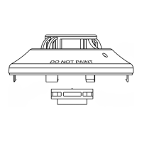
Instructions for mounting the base, including hole punching and securing to the junction box.

Terminal Identification and Wiring

Details the four terminals on the base and their connection purposes for detection zone and alarm output.

Wiring and Installation Guidance

Recommended Wiring Specifications

Specifies minimum cable size and notes on avoiding wiring mistakes for conventional devices.

Detector Mounting Procedure

Describes how to fix the base to the electrical box and rotate the detector onto the base.

Testing Procedures

Testing Preparation and Notification

Ensures the detector is installed and powered, and authorities are notified of system maintenance.

Smoke Entry Testing Methods

Details using a magnet (reed switch) and aerosol testers for smoke entry and alarm verification.

Post-Testing System Restore

Covers cutting power, resetting the detector, and restoring the system to normal operation.

Maintenance and Cautions

Annual Detector Cleaning

Provides steps for cleaning the sensing chamber using vacuum or compressed air, and water if needed.

Operational Cautions

Highlights warnings regarding dust covers, detector limitations, and fire scenarios not detected.

Regular Testing and Service Life

Emphasizes the need for annual testing and maintaining detectors according to standards for their service life.

Specifications

Electrical and Environmental Ratings

Lists operating voltage, current draw, temperature, humidity, and ingress protection ratings.

Physical and Compatibility Data

Details dimensions, mounting spacing, weight, and compatibility with specific control panels.
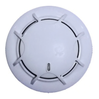
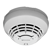
Related product manuals