Do you have a question about the Edwards Signature Series and is the answer not in the manual?
Provides essential operational and safety notes for detector installation, covering power, smoke detection limitations, and storage.
Step-by-step instructions for physically attaching the SIGA-PD detector to its base.
Procedures to verify the detector's correct address, trouble signals, and system responses upon initial setup.
Steps to perform a specific test on the detector's sensing capabilities.
Guidance for planning detector maintenance in accordance with governing standards and authorities.
Detailed technical parameters including operating voltage, current, vibration, air velocity, and environmental limits.
Compliance details for North American standards, FCC, and Industry Canada.
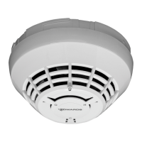
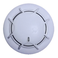
The SIGA-PD Intelligent Photoelectric Smoke Detector is a sophisticated device designed to detect smoke using an optical sensing chamber. This intelligent detector analyzes data from its sensing chamber to determine whether an alarm condition exists, providing early warning in the event of a fire. It is particularly well-suited for detecting slow, smoldering fires due to the nature of photoelectric sensing technology.
The core function of the SIGA-PD detector is to identify the presence of smoke. It achieves this through an optical sensing chamber that continuously monitors the air. When smoke particles enter this chamber, they scatter light, which is then detected by the device. The detector's intelligent processing capabilities analyze this scattered light data to differentiate between actual smoke conditions and other environmental factors, thereby minimizing false alarms.
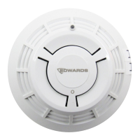
The detector communicates its status through an integrated LED indicator. In normal operating conditions, this LED flashes green, indicating that the device is functioning correctly and no smoke has been detected. If smoke is detected and an alarm condition is initiated, the LED flashes red, serving as a clear visual alert to evacuate the area.
For installation, the detector is designed to be attached to a compatible base by rotating it clockwise until it securely snaps into a locked position. This modular design simplifies installation and replacement. The device requires electrical power to operate, and it is important to consider that power interruptions can occur during fires. Therefore, consulting with a local fire protection specialist for additional safeguards is recommended.
The SIGA-PD detector is designed to integrate with fire alarm control panels that can perform system sensitivity reports. This allows for calibrated sensitivity testing, ensuring the detector operates within acceptable limits as per NFPA code. The device's intelligence also supports the generation of system sensitivity reports by the panel, aiding in compliance and performance verification.
The SIGA-PD detector offers several features that enhance its usability and reliability in various applications. It is crucial to understand that the detector will not sense fires in areas where smoke cannot reach it, such as inside walls, roofs, or behind closed doors. Proper placement is therefore essential for effective fire detection.
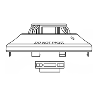
During installation, a dust cover is supplied and must remain on the detector. This cover protects the device from dust and debris during construction or remodeling, but it must be removed prior to commissioning and service to ensure proper operation. It is important to note that the dust cover is not a substitute for removing the detector itself during heavy remodeling or new construction.
The detector should be stored within recommended temperature ranges and allowed to stabilize to room temperature before power is applied to ensure proper operation. This helps maintain the integrity of the sensing components.
For specific applications, such as installation in air ducts, the SIGA-PD detectors require verification that the airflow is within specified limits. This ensures that smoke can effectively reach the sensing chamber. The device is compatible with various bases, including standard, relay, isolator, and audible bases, offering flexibility in system design.
The SIGA-PD detector is designed to be compatible with specific detector testers, such as Testifire 1000 and Testifire 2000, which facilitate functional testing. When performing a sensor function test, the fire alarm control panel can be used to place the detector or zone into a service group for testing, preventing unnecessary alarms during maintenance.
Regular maintenance is critical to ensure the continued proper operation of the SIGA-PD Intelligent Photoelectric Smoke Detector. Maintenance should be planned and executed in accordance with the Authority Having Jurisdiction (AHJ) and all applicable governing laws, codes, and standards, including CAN/ULC-S536 Standard for the Inspection and Testing of Fire Alarm Systems and NFPA 72 National Fire Alarm and Signaling Code.
Before any testing or maintenance, it is essential to notify the proper authorities that the fire alarm system will be temporarily out of service. This prevents unwarranted dispatches and ensures safety protocols are followed.
An initial installation test involves several steps to verify the detector's functionality. This includes removing the detector from its base to confirm that the proper detector address, trouble signals, and messages are reported by the control panel. For Class A wiring configurations, it is necessary to verify that the detector continues to operate correctly even when SLC_IN and then SLC_OUT are disconnected, demonstrating the system's resilience.
A momentary ground fault on the SLC circuit should be introduced to verify the operation of the ground fault detection circuitry, an important safety feature. After installation, a system detector sensitivity report should be run on all detectors to confirm that their readings fall within acceptable limits. This ensures that each detector is calibrated and functioning optimally.
For sensor function testing, the use of smoke aerosol sprays or smoke generators, such as No Climb Products model Smoke Centurion/M8, FireTech Smoke, or Smoke Sabre, is recommended. Alternatively, a Testifire detector tester can be used according to the manufacturer's instructions. This ensures that the detector responds appropriately to the presence of smoke.
The detector also features automatic environmental compensation, which helps maintain consistent performance despite changes in ambient conditions. This reduces the need for frequent manual adjustments and enhances reliability.
In summary, the SIGA-PD Intelligent Photoelectric Smoke Detector is a reliable and intelligent device designed for effective smoke detection. Its features, from optical sensing and LED indicators to flexible installation options and comprehensive maintenance protocols, ensure its role as a critical component in a robust fire alarm system. Adherence to installation guidelines, regular testing, and scheduled maintenance are paramount to maximizing its performance and ensuring life safety.
| Alarm Sound Level | 85 dB at 10 feet |
|---|---|
| Power Source | 120V AC, 9V DC battery backup |
| Operating Humidity | 10% relative humidity |
| Hush Feature | Yes |
| Compliance | UL 217 |
| Operating Temperature | 40°F to 100°F (4°C to 38°C) |