8 R-Series Remote Annunciators and Expanders Installation and Operation Guide
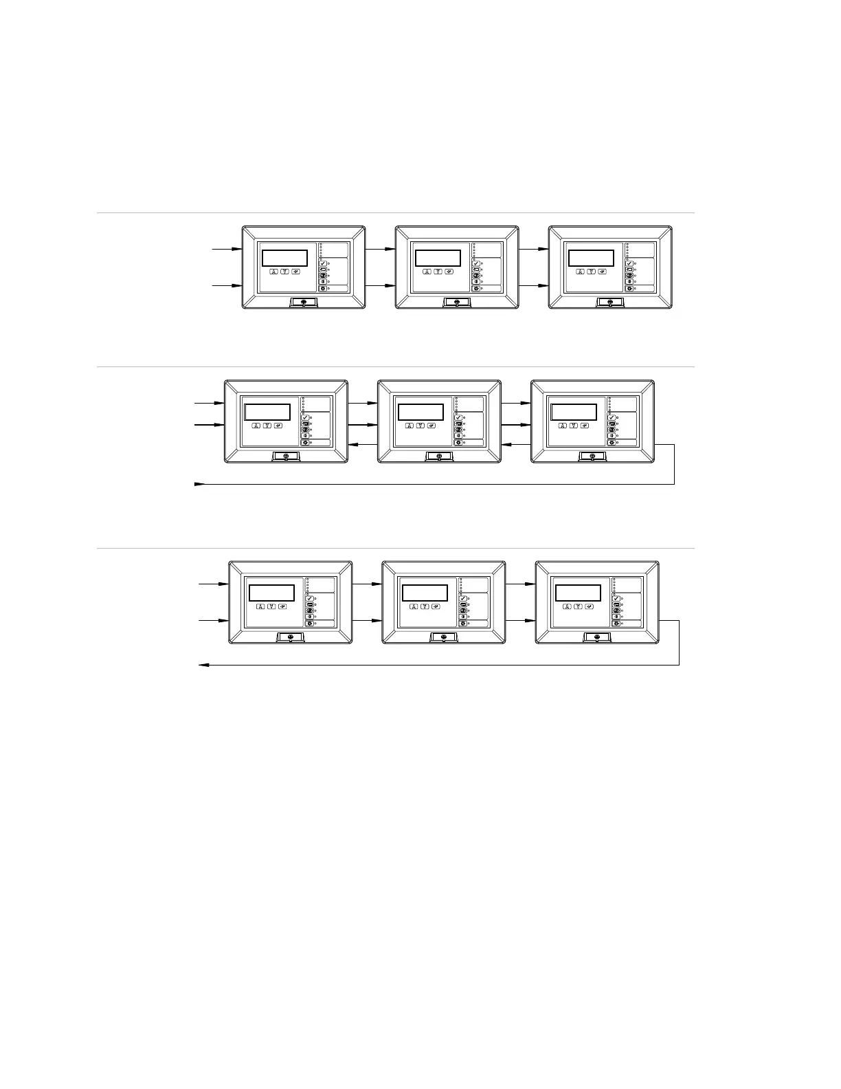
Wiring diagrams
All wiring is supervised and power-limited, unless otherwise noted. For terminal
connections, refer to the documents listed on the control panel label.
Figure 5: Typical Class B wiring
Figure 6: Typical redundant Class B wiring
Figure 7: Typical Class A wiring
AUX_POWER
Controls Enabled
Ack/Silence
Reset
Signal Silence
Drill
Lamp Test
Power
Alarm
Supervisory
Ground Fault
Trouble
Contro ls Enabled
Ack/Silence
Reset
Signal Silence
Drill
Lamp Test
Power
Alarm
Supervisory
Ground Fault
Trouble
Controls Enabled
Ack/Silence
Reset
Signal Silence
Drill
Lamp Test
Power
Alarm
Supervisory
Ground Fault
Trouble
RS-485_BUS_B /
ANN_CH1
ANN_CH1
UX_POWE
Controls Enabled
Ack/Silence
Reset
Signal Si lence
Drill
Lamp Test
Power
Alarm
Superv isory
Ground Fault
Trouble
Controls Enabled
Ack/Silence
Reset
Signal Silence
Drill
Lamp Test
Power
Alarm
Supervisory
Ground Fault
Trouble
Controls Enabled
Ack/Silence
Reset
Signal Silence
Drill
Lamp Test
Power
Alarm
Superv isory
Ground Fault
Trouble
ANN_CH2
AUX_POWER
Controls Enabled
Ack/Silence
Reset
Signal Silence
Drill
Lamp Test
Power
Alarm
Supervi sory
Ground Fault
Trouble
Controls Enabled
Ack/Silence
Reset
Signal Silence
Drill
Lamp Test
Power
Alarm
Supervisory
Ground Fault
Trouble
Control s Enabled
Ack/Silence
Reset
Signal Silence
Drill
Lamp Test
Power
Alarm
Supervisory
Ground Fault
Trouble
RS-485_BUS_B
RS-485
BUS
A
 Loading...