EasyManua.ls Logo

Efka AB320A5200 User Manual

Default Icon
78 pages
To Next Page IconTo Next Page
Page #1 background imageLoading...
Page #1 background image
CONTROL AB320A5200
LIST OF PARAMETERS
CONNECTION DIAGRAM
TIMING DIAGRAMS
No. 402286 English
FRANKL & KIRCHNER EFKA OF AMERICA INC. EFKA ELECTRONIC MOTORS
GMBH & CO KG SINGAPORE PTE. LTD.
+
-
>>
P
E
0
I
KL2334a
Question and Answer IconNeed help?

Do you have a question about the Efka AB320A5200 and is the answer not in the manual?

Efka AB320A5200 Specifications

General IconGeneral
BrandEfka
ModelAB320A5200
CategoryControl Unit
LanguageEnglish

Summary

Table of Adapter Cords

Putting into Service

Setting and Putting into Service with the Aid of the Fast Installation Routine (SIR)

Operating Elements and Socket Connectors

Position of Operating Elements and Displays

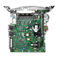
Details the location and function of control buttons and indicators on the device.

Position of the Socket Connectors

Identifies the purpose and location of various input/output sockets on the unit.

Connection Diagram

Illustrates the electrical wiring and connections for system integration.

Connection of a Sewing Light with Transformer

Provides instructions for safely connecting a sewing light accessory to the control unit.

Adapter Cords

Details specific adapter cords required for connecting various sewing machine models.

Timing Diagrams

List of Parameters

Preset Values Depending on Mode

Presents default parameter values that automatically adjust based on the selected operational mode.

Operator Level

Lists parameters accessible and adjustable by the end-user for normal operation.

Technician Level

Details parameters for advanced configuration and maintenance by trained technicians.

Supplier Level

Lists parameters for advanced configuration, calibration, and system settings.

Error Displays

Slide-in Strips for the V810/V820 Control Panels

Related product manuals