Using the EF-Series Unit
2-22 Rev 2/01
The RTD terminals on the Main Electronics Board are designated and defined as follows:
♦ “REF” current source reference
♦ “+” signal positive input
♦ “-” signal negative input
♦ “RET” return (common) reference
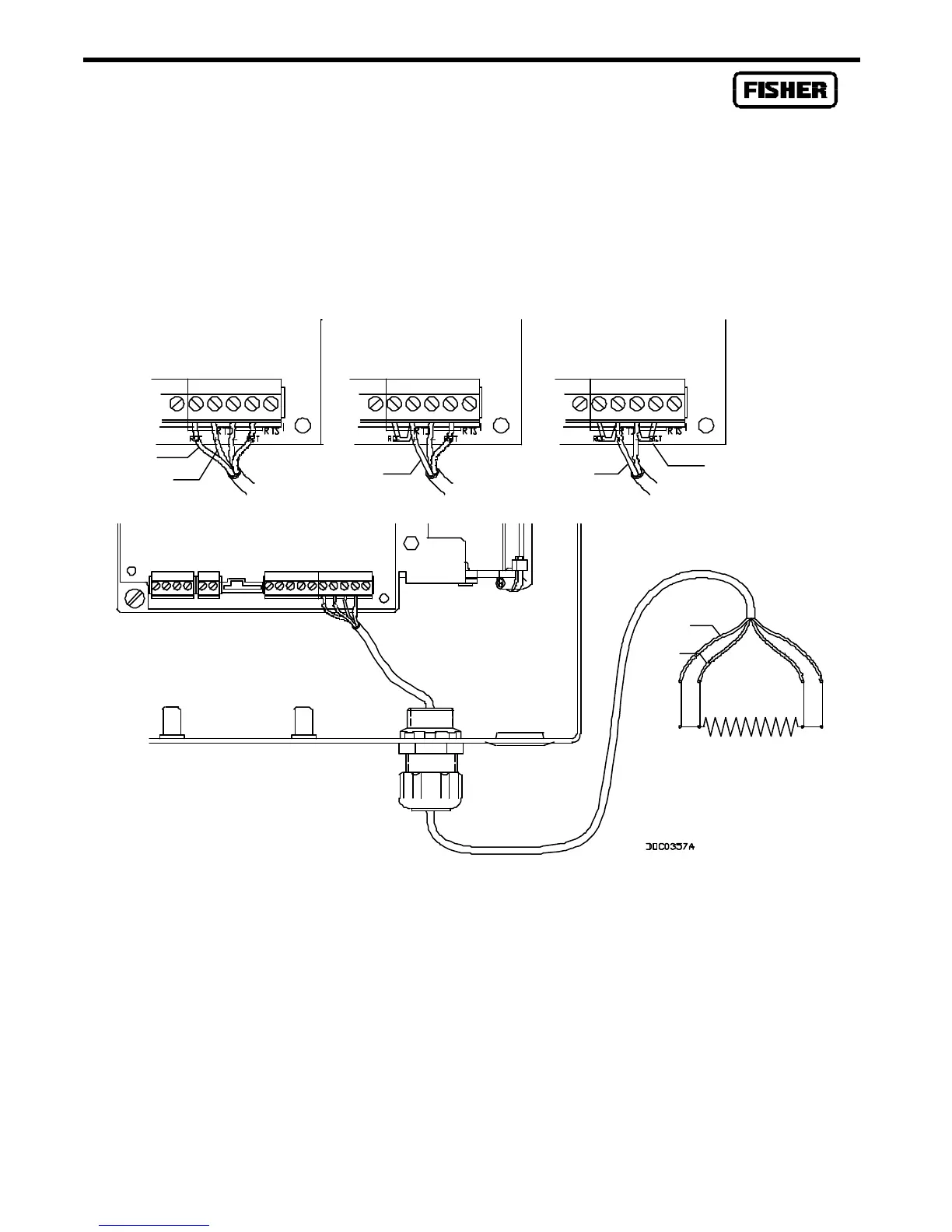
Figure 2-6. RTD Wiring Terminal Connections
As shown in Figure 2-6, the connections at the RTD terminals for the various RTD probes are as
follows:
Terminal 4-Wire RTD 3-Wire RTD 2-Wire RTD
REF Red Jumper to + Jumper to +
+ Red Red, Jumper to REF Red, Jumper to REF
– White White White, Jumper to RET
RET White White Jumper to –
RTD Sensor
Red
Red
RedRed
Red
Red
Jumper