EF-Series Instruction Manual
Rev 2/01 2-21
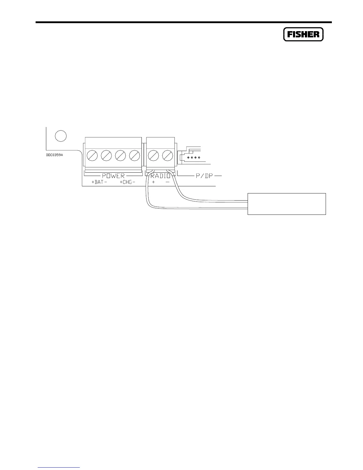
2.5.4 Auxiliary Output Power
The auxiliary output power connections are on a fixed terminal block connector labeled RADIO.
Refer to Figure 2-5. These terminals can supply power (pass-through) to external devices such as a
radio. The power for this connector originates at the battery connection terminal and is not fused or
controlled on the Main Electronics Board. Fusing should be installed in the auxiliary output wiring
and should not exceed the size of the fuse in the battery harness wiring. The terminals are labeled “+”
for positive voltage and “-” for common.
Figure 2-5. Auxiliary Power Terminals
If power to the radio or other device needs to be cycled to conserve power (recommended when
batteries are used), use an EIA-232 communications card and connect wiring for switched radio power
as described in Section 3. Configure Radio Power Control as detailed in the ROCLINK Configuration
Software User Manual.
2.5.5 RTD Wiring
The temperature is input through the Resistance Temperature Detector (RTD) probe and circuitry. An
RTD temperature probe mounts directly to the piping using a thermowell, outside the EF-Series
enclosure. RTD wires should be protected either by a metal sheath or conduit connected to a liquid-
tight conduit fitting on the bottom of the enclosure. The RTD wires connect to the four screw
terminals designated “RTD” on the Main Electronics Board. Refer to Figure 2-6.
The EF-Series unit provides terminations for a four-wire 100-ohm platinum RTD with a DIN 43760
curve. The RTD has an alpha equal to 0.00385. A three-wire or two-wire RTD probe can be used
instead of a four-wire probe; however, they may produce measurement errors due to signal loss on the
wiring.
Wiring between the RTD probe and the EF-Series unit must be shielded wire, with the shield grounded
only at one end to prevent ground loops. Ground loops cause RTD input signal errors.
Radio or other constant-
powered device