7
GB-031C_f
LED
1
2
3
4
5
LED
Rated
power
[kW]
Pump lifting
height [m]
LED 1
red
LED 2
yellow
LED 3
yellow
LED 4
yellow
LED 5
yellow
4
● ●
6-9 5
● ● ●
9-12 6
● ● ● ●
14 - 39 7
● ● ●
If the pump has detected one or more alarms, the bicolored LED
1 switches from green to red. When an alarm is active, the LEDs
indicate the alarm type as defined in the table below. If multiple
alarms are active at the same time, the LEDs only show the error
with the highest priority. The priority is defined by the sequence of
the table. When there is no active alarm anymore, the user interface
switches back to operation mode.
One red LED + one
yellow LED (LED 5)
Rotor is
blocked.
Trying to start
again every 1,5
seconds
Wait or
deblock the
shaft.
One red LED + one
yellow LED (LED 4)
Supply volt-
age too low
Only warning
pump runs
Control the
supply volt-
age
One red LED + one
yellow LED (LED 3)
Electrical
error
Pump is stopped
because of low
supply voltage or
serious failure
Control the
supply voltage
/Exchange the
pump
IF SUPPLIED WITH THE GRUNDFOS UPM3 PUMP
1. Ensure the system is filled with water and correctly vented.
2. Check if the appropriate system installation pressure is reached
(see the “TECHNICAL DATA” section) by pressing the down
arrow button whilst the control panel is off, the pressure value
will be displayed. When the installation pressure is too low The
“A’’indicator flickers (see “Operating’’ section). This doesn’t
concern open vented system installations.
3. Set the external controls to call for heat.
4. Switch the boiler on by pressing the power button.
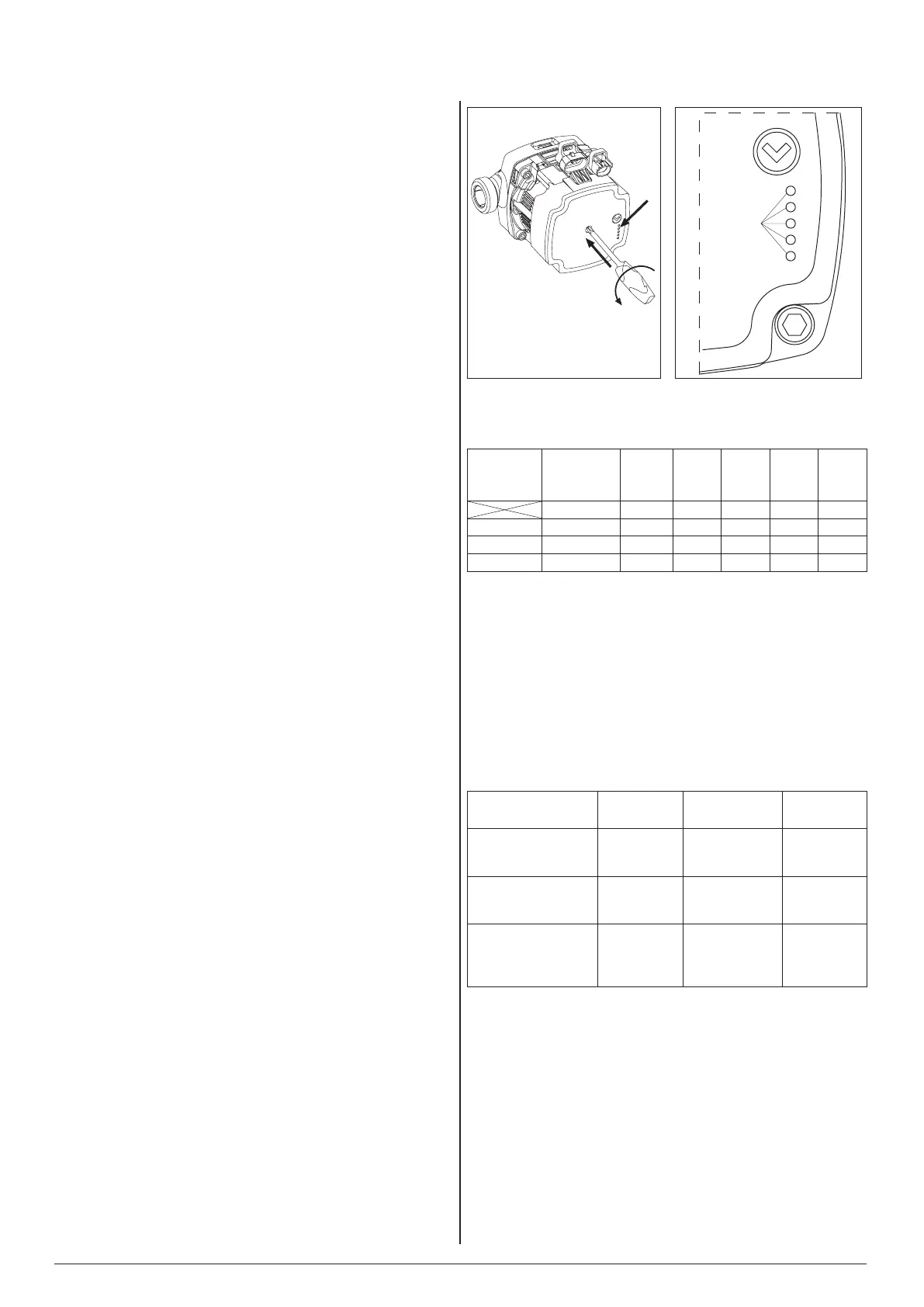
5. Check the pump is set to the correct mode (see table 15.1).
To do this, press the pump arrow button for no more than 2
seconds. The LED’s should signal an operating mode at the
place pointed by arrow.
6. If the LEDs are signalling a different operating mode than
recommended in table 15.1, set the appropriate mode according
to the following instructions: press the pump arrow button for
longer than 2 seconds, but less than 10 seconds (LED’s will start
to flash),the pump then switches to the programming mode.
LEDs glows to indicate the current settings. To change the
settings of the pump in accordance with table 15.1, you can set
the right combination of glowing LEDs by pressing the pump
arrow button. Once the LED combination is set correct, by not
pressing the button for 10 seconds the pump will remember
this setting and will exit from the programming mode back to
performance view.
7. Ensure adequate flow through the boiler is reached (the ‘H’
indicator is on with a constant light). The pump should self vent
after a short period of running. If necessary assist the venting
process in the following way; Warning the screw head in the
centre of the pump is not intended to be used to assist venting
of the pump, Damage to the pump internals may occur!
• close the isolation valve on the outlet,
• leave boiler running for 15 sec.
• open the isolation valve.
8. Set the external controls to the required program and the boiler
to the required system temperature, see the “Operating” section.
Table 15.1
Table 15.2


 To Next Page
 Loading...