M2CP Digital Futronic User Manual
84829 Rev F
EIM Company, Inc 13840 Pike Road Missouri City, TX 77489 (281) 499-1561 Page 3
M
ODULE
S
ETUP AND
C
ALIBRATION
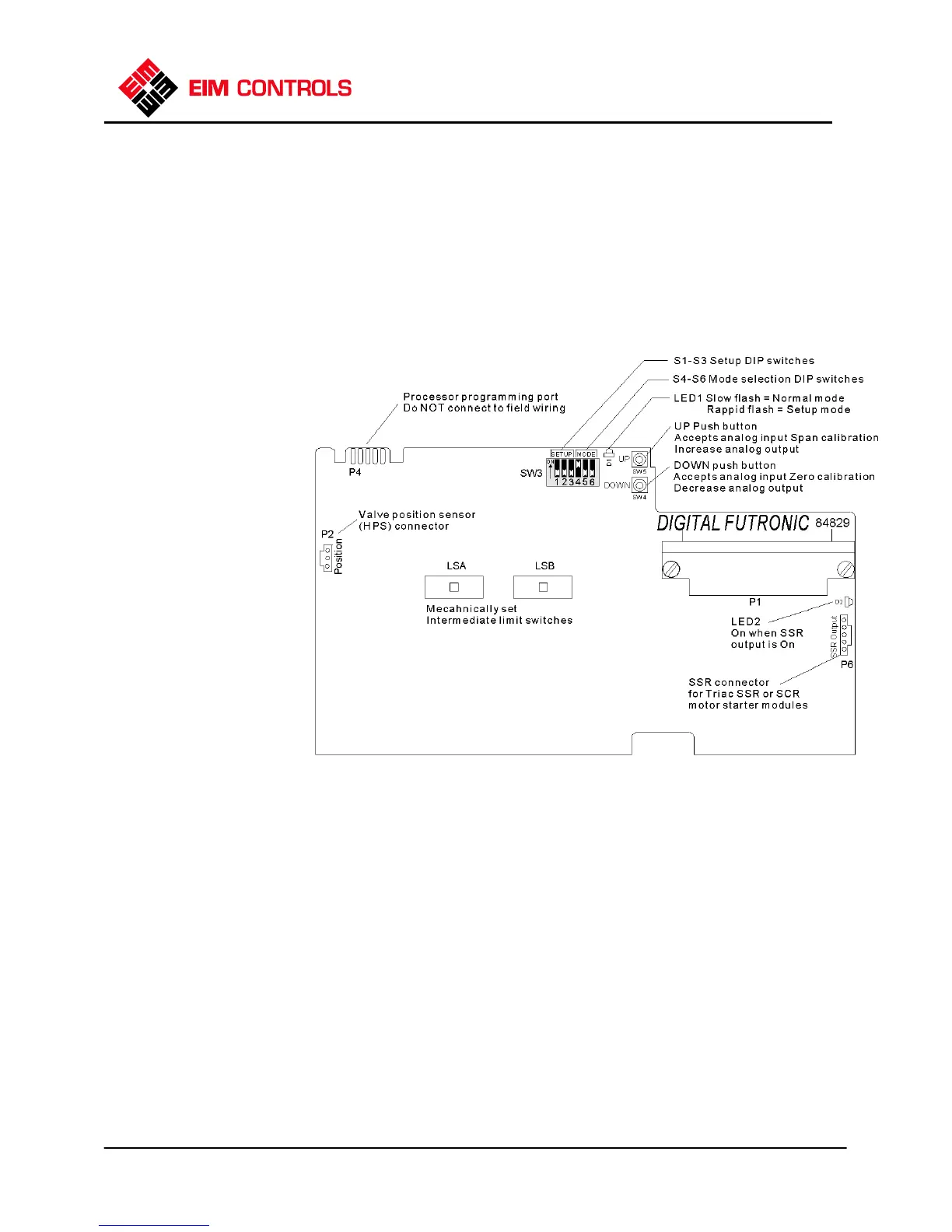
DIP Switch SW3 has 6 switches designated as S1-S6 for calibration and mode selection as summarized
below. There are two miniature push buttons labeled UP and DOWN. Refer to Figure 2 for location of DIP
switches and push buttons. Switches S1-S3 are used for setup and calibration and switches S4-S6 are
used for mode selection. If any one or more of switches S1, S2 or S3 are on, the actuator is in setup
mode. The actuator returns to normal operating mode when all three switches S1-S3 are turned off.
When changing from setup mode to normal operating mode, do not turn off power to the actuator for at
least 5 seconds to allow the controller to store the new setup values to EEPROM nonvolatile memory.
Setup and normal operating modes are designated by LED 1 as defined below.
F
IGURE
2
F
IRMWARE
V
ERSION
N
UMBER
D
ISPLAY
Each time the actuator is powered up, the firmware version number is displayed by LED1 with the
following sequence of flashes.
At power up LED1 stays on for 4 seconds and then begins to flash. Count the number of times the LED
flashes on before it turns on solid again for 2 seconds. The number of flashes is the high order firmware
version number.
After a 2-second solid on delay, the LED will begin to flash again. Count the number of flashes until the
LED turns on solid again for 4 seconds. The number of flashes is the low order firmware version number.
After the 4-second delay, LED1 will then flash at the normal rate defined under Indicator Lights above.
If unable to correctly count the number of flashes to properly determine the firmware version number,
then cycle power to the actuator and the display process will repeat.
NDICATOR
IGHTS
LED 1
► Slow Flash =
Normal Operating Mode.
► Rapid Flash =
Setup mode (any one of
switches S1 through S3
are on).
► Alternating Between
Slow and Rapid Flash =
Lost Analog Input
(Command) Signal.
► Steady On or Steady
Off = Module failure.
LED2
► On when Solid State
Relay (SSR or SCR) is On
(control power applied to
output).
 Loading...