Do you have a question about the EINHELL BT-BD 501 and is the answer not in the manual?
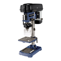
This document serves as the original operating instructions for the Einhell BT-BD 501 Bench Drill, identified by Article Number 42.505.42 and I.-Nr.: 11012. It provides essential information for safe and effective operation, maintenance, and troubleshooting of the device.
The Einhell BT-BD 501 Bench Drill is designed for drilling into various materials such as metal, plastic, wood, and similar substances. It is intended for private sector use, not for commercial, trade, or industrial applications. The drill chuck is specifically designed for drill bits and tools with a shaft diameter ranging from 1.5 to 16 mm, accommodating both cylindrical tool shanks and tools with tapered shanks. The equipment is intended for use by adults only. It is crucial to use the drill only for its prescribed purpose; any other use is considered misuse, and the user/operator will be held liable for any resulting damage or injuries. The manual explicitly states that food and harmful materials should not be processed with this equipment.
Before commencing any operation, it is imperative to read and understand all safety information and instructions provided in the manual and the accompanying safety booklet. Failure to adhere to these guidelines can lead to electric shock, fire, or serious injury. All safety information and instructions should be kept in a safe place for future reference. The manual highlights several safety precautions, including wearing ear-muffs to prevent hearing damage from noise impact and safety goggles to protect against sparks, splinters, chips, and dust that could cause loss of sight.
The assembly process begins by positioning the machine base (1), followed by fastening the mounting flange with the pillar (2) using three screws (3) and washers. The drill table (4) with its clamp shaft is then pushed onto the pillar (2) and locked into the desired position with the clamping screw (5). The drill head (6), which includes the V-belt cover (7) and motor (8), is placed onto the drill pillar and secured with Allen screws (20). Finally, the three ball-shaped handles (9) are screwed onto the feeder cross handle. A critical note emphasizes that all bare parts are greased for corrosion protection, and before mounting the drill chuck (10) onto the spindle (11), both parts must be thoroughly degreased with an environmentally friendly solvent to ensure optimal power transmission.
For initial use, the drill must be permanently fixed in position using the two mounting holes (12) in the base plate. This ensures stability and safety during operation. It is important that the fixing screws are tightened only to the point where they do not distort or deform the base plate, as excessive tension can lead to fracture. The hinged chip guard (13) is an essential safety feature. To install it, three screws (21) are unscrewed, the transparent cover (23) is pushed into the groove of the red mounting frame (24), and then refastened with the screws (21). The chip guard (13) is then attached to the machine using the clamping screw. After installation, the chip guard can be swung up to change drill bits, but it must be returned to its initial position before restarting the equipment. The height of the cover (23) is infinitely adjustable and can be locked with two thumb screws (22).
Operating the drill involves a straightforward process. To switch on, the green "I" button (18) is pressed, and to switch off, the red "O" button (19) is pressed. Users are cautioned not to overload the equipment; if the motor's sound pitch drops, it indicates an overload. The motor should never be allowed to come to a standstill due to overload. Before changing tools, the power plug must always be removed from the socket-outlet. Only cylindrical tools within the specified shaft diameter range (1.5 to 16 mm) should be clamped in the drill chuck (10). Tools must be sharp, free of defects, and undamaged. The quick-change drill chuck (10) is gear-toothed. To insert a drill bit, the chip guard (13) is flipped up, the drill bit is inserted, and the drill chuck is tightened using the supplied chuck key. The chuck key must then be removed from the clamp hole to prevent injury from it being catapulted out during operation.
The various spindle speeds can be adjusted by moving the V-belt. First, the equipment must be switched off, and the power plug pulled. To access the V-belt, the screw (16) is removed to open the V-belt cover (7). The tightening screw (15) is slackened, and the motor (8) is pushed towards the machine head. The V-belt is then moved to the desired position, referring to the provided table (Fig. 8) for recommended speeds. After adjustment, the V-belt is tightened by pushing the motor (8) away from the drill head (6), and the tightening screw (16) is screwed back down. Proper tension is achieved when the V-belt flexes approximately 1 cm in the middle when pressed. Finally, the V-belt cover (7) is closed and secured with screw (16). The V-belt cover (7) must always be locked tightly, as the equipment has a safety switch that prevents operation when the cover is open. It is crucial never to let the pillar drill run with the V-belt cover open and always to pull the power plug before opening the cover or touching the V-belt when it is rotating.
The drill depth stop (Fig. 10) allows for precise drilling depth. The drilling spindle features a swiveling scale ring (25). Adjustments should only be made when the equipment is at a standstill. To set the depth, the drilling spindle (11) is pressed downwards until the drill bit tip touches the workpiece. The clamping screw (17) is slackened, and the scale ring (25) is turned forwards until it stops. The scale ring (25) is then turned back to the desired drill depth and locked into place using the clamping screw (17). When setting the drill depth for a cylindrical hole, the length of the drill tip must be added to the desired depth.
The angle of the drill table (Fig. 7) can be adjusted by slackening the carriage bolt (26) under the drill table (4), setting the table to the desired angle, and then tightening the carriage bolt (26) to lock it in position. Similarly, the height of the drill table (Fig. 1) is adjusted by slackening the tightening screw (5), moving the drill table (4) to the desired height (by pressing down or lifting up and gently pushing left or right), and then screwing the tightening screw (5) back down.
Workpiece clamping is critical for safety. A machine vice or another suitable clamping device should always be used to secure the workpiece. Never hold the workpiece by hand. For self-centering, the workpiece should be able to travel on the drill table (4), and it must be ensured that the workpiece cannot rotate. This is best achieved by placing the workpiece/machine vice on a sturdy block. Sheet metal parts must be clamped to prevent tearing. The height and angle of the drill table should be set appropriately for each workpiece, ensuring sufficient distance between the upper edge of the workpiece and the drill bit tip.
Working speeds are dependent on the drill bit diameter and the material. The manual provides a table (Fig. 8) as a guide for selecting appropriate speeds for various materials, emphasizing that these are suggested values. The drill can also perform countersinking and center-drilling. Countersinking should be done at the lowest speed, while center-drilling requires a high speed. When working with wood, proper evacuation of sawdust is necessary due to health hazards, and a suitable dust mask should be worn.
Maintenance primarily involves keeping the equipment clean. Before any cleaning or maintenance, the power plug must be pulled. Harsh or abrasive solvents should not be used, and no liquid should seep into the equipment. All bare parts, especially the drill pillar, blank parts of the column, and the drill table, should be regreased at regular intervals with a standard, acid-free lubricating grease. Oil and grease-soaked cleaning rags or sludge should be disposed of in an environmentally friendly manner, not in household trash. Ventilation holes should be checked and cleaned regularly. The equipment should be stored in a dry room. Users are advised not to attempt repairs themselves; any damaged equipment should be handled by a qualified electrical technician. Regular cleaning with a damp cloth and soft soap is recommended, avoiding cleaning agents or solvents that could damage plastic parts. No water should enter the equipment's interior. The equipment is largely maintenance-free, with no parts requiring additional maintenance inside.
For ordering replacement parts, customers should provide the equipment's model/type, article number, ID number, and the required spare part number. Information on prices can be found on www.einhell.com.au. The equipment and accessories should be stored out of children's reach, in a dark, dry place, above freezing temperature, ideally between 5 and 30 °C, and in its original packaging. The equipment is supplied in packaging for transit protection, and these raw materials can be reused or recycled. Defective components should be disposed of as special waste, and users should consult their dealer or local council for guidance.
| Power | 500 W |
|---|---|
| Chuck Capacity | 1.5 - 13 mm |
| Drilling Capacity in Steel | 13 mm |
| Drilling Capacity in Wood | 30 mm |
| Weight | 9.5 kg |
| Number of speed settings | 2 |
| Max. drilling depth | 50 mm |
| Voltage | 230 V |
| Chuck Size | 13 mm |
| Drill chuck | Keyless |