EN
- 11 -
Pull the sleeve (Fig. 9/Item 8.1) to the top end of
the blower tube (Fig. 9/Item 8) as shown in Fig. 9.
Make sure that it snaps in place correctly on both
sides.
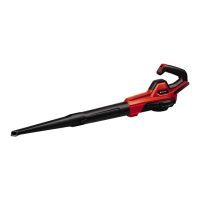
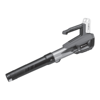
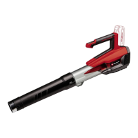
5.2.1 Assembly in blower mode (Fig. 10/11)
Insert the blower tube (Fig. 10/Item 8), which was
prepared in 5.1, into the mount (Fig. 10/Item 8.2)
on the motor housing. Make sure that it latches in
place correctly.
Fit the shoulder strap (Fig. 11/Item 4) to the motor
housing as shown in Fig. 11.
To dismantle, proceed in reverse order. To remove
the blower tube, press the button (Fig. 10/Item
8.3) and pull off the blower tube.
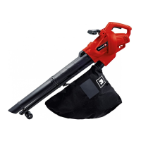
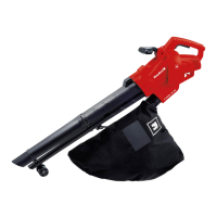
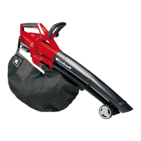
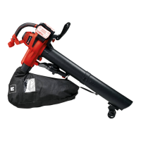
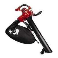
5.2.2 Assembly in vacuum mode (Fig. 12-17)
Undo the lock knob (Fig. 12/Item 12.1) and pull
open the cover (Fig. 12/Item 13). Attach the
vacuum tube (Fig. 13/Item 2), which was prepared
in 5.1, to the motor housing and snap it onto the
motor housing as shown in Fig. 13. Now secure it
with the lock knob (Fig. 14/Item 3.1).
Fit the shoulder strap (Fig. 15/Item 4) to the motor
housing as shown in Fig. 15.
Connect the collection bag (Fig. 16/Item 7) to the
mount (Fig. 16/Item 7.1) on the motor housing.
Make sure that it latches in place correctly.
Secure the collection bag by the two hooks on the
vacuum tube as shown in Fig. 17.
To remove the collection bag, press the button
(Fig. 16/Item 7.2) and pull off the collection bag.
To dismantle the rest, proceed in reverse order.
Start up the equipment only when fully
assembled. Always inspect the power cord for
damage before starting up. The equipment may
be used only if the cord is in fl awless condition.
There are a number of safety switches for
preventing the unsafe operation of the equipment.
Make sure, therefore, that the following
components are correctly fastened, otherwise it
will not be possible to switch on the machine.
•
In blower mode: Blower tube (Fig. 10/Item 8)
and cover (Fig. 12/Item 13).
•
In vacuum mode: Suction tube (Fig. 13/Item
2) and collection bag (Fig. 16/Item 7)
6. Operation
6.1 Sizing the shoulder strap (Fig. 1)
Size the length of the shoulder strap (4) so that
the vacuum tube just clears the ground. The
castors (9) at the bottom end of the suction tube
will help you to maneuver the suction tube on the
ground.
6.2. Connecting the equipment to the power
supply and switching on (Fig. 18/19)
The equipment can be connected to any socket-
outlet (with 120V ~) that is equipped with a
15A fuse or higher. The socket-outlet has to be
safeguarded by an earth-leakage circuit breaker
(e.l.c.b.).
The operating current must not exceed 30 mA.
•
Connect the equipment's plug into an
extension cord.
•
Secure the extension cord with the strain-
relief clip provided on the equipment as
shown (Fig. 18).
•
To switch on, push the On/Off switch to the "I"
position.
•
To switch off, push the On/Off switch to the
"O" position.
6.3 Emptying the collection bag (Fig. 1)
Empty the collection bag (7) in good time. When
the bag is heavily loaded with material, vacuum
power is considerably reduced. Deposit organic
refuse at a compost site.
•
Switch off the tool and pull out the plug.
•
Open the zipper on the collection bag (7) and
shake out the material.
•
Close the zip on the collection bag (7).
6.4 Speed control (Fig. 2)
The device is fi tted with an electronic speed
controller. To use it, turn the speed controller (Fig.
2/ Item 10) to the desired position. Use the device
only with the speed which is actually required and
do not let it run at a speed which is faster than
necessary.
Anl_GC_EL_3000_E_SPK7_USA.indb 11Anl_GC_EL_3000_E_SPK7_USA.indb 11 16.12.2022 08:30:3016.12.2022 08:30:30