GB
- 21 -
Take care that the safety device is secure.
Never use the angle grinder without the
guard.
5.3 Test run for new grinding Wheels
Allow the right-angle grinder to run in idle for at
least 1 minute with the grinding or cutting wheel
fi tted in place. Vibrating wheels are to be replaced
immediately.
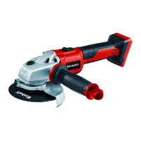
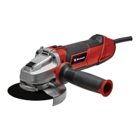
6. Operation
6.1 Switch (Fig. 4)
The angle grinder comes with a safety switch
which is designed to prevent accidents. To switch
on, push the On/Off switch (2) to the right and
then forwards. To switch off the angle grinder,
depress the ON/OFF switch (2) at the back. The
ON/OFF switch (2) will jump back into its starting
position.
Wait until the machine has reached its top
speed. You can then position the angle grin-
der on the workpiece and machine it.
6.2 Changing the grinding wheels (Fig. 5 / 6)
Use the face spanner (5) supplied to change the
grinding wheels. The face spanner (5) is stored in
the additional handle (3). Pull the face spanner (5)
out of the additional handle (3) when you need it.
Important! For safety reasons, the angle grinder
must not be operated with the face spanner (5)
inserted in it.
Pull out the power plug.
•
Simple wheel change by spindle lock:
•
Press the spindle lock and allow the grinding
wheel to latch in place.
•
Open the flange nut with the face spanner.
•
(Fig. 6)
•
Change the grinding or cutting wheel and
tighten the flange nut with the face spanner.
Important!
Only ever press the spindle lock when the
motor and grinding spindle are at a stand-
still! You must keep the spindle lock pressed
while you change the wheel!
For grinding or cutting wheels up to approx. 3 mm
thick, screw on the fl ange nut with the fl at side
facing the grinding or cutting wheel.
6.3 Flange arrangements when using grin-
ding wheels and cutting wheels (Fig.
7-10)
•
Flange arrangement when using a de-
pressed-centre or straight grinding wheel
(Fig. 8)
•
a) Clamping flange
•
b) Flange nut
•
Flange arrangement when using a de-
pressed-centre cutting wheel (Fig. 9)
•
a) Clamping flange
•
b) Flange nut
•
Flange arrangement when using a straight
cutting wheel (Fig. 10)
•
a) Clamping flange
•
b) Flange nut
6.4 Motor
It is vital for the motor to be well ventilated during
operation. Be sure, therefore, to keep the ventilati-
on holes clean at all times.
6.5 Grinding Wheels
•
Never use a grinding or cutting wheel bigger
than the specified diameter.
•
Before using a grinding or cutting wheel,
check its rated speed.
•
The maximum speed of the grinding or cut-
ting wheel used must be higher than the idle
speed of the angle grinder.
•
Use only grinding and cutting wheels that are
approved for a minimum speed of 11,000 rpm
and a peripheral speed of 80 m/sec.
•
Check the direction of rotation when you use
diamond cutting wheels. The directional arrow
on the diamond cutting wheel must point in
the direction in which the tool rotates.
Take special care that the grinding/sanding
wheels are properly stored and transported.
Ensure that the grinding/sanding wheels are
never exposed to shock, jolts or sharp edges (for
example during transport or storage in a toolbox).
This could cause damage (such as cracks) to the
grinding/sanding wheels and place the user in
serious danger.
Anl_TE_AG_115_SPK1.indb 21Anl_TE_AG_115_SPK1.indb 21 06.09.12 10:5506.09.12 10:55