6
3 INSTALLATION AND OPERATION
The product shall be installed onto 35 mm DIN rail in the
distribution enclosure.
In order to avoid pickup, false triggering, improper operation of the
timer, don’t put the supply conductors together with power wiring.
Use the shielded cable if necessary.
Copper and aluminum wire with cross-section of max. 4 mm2
connections are supported. Before connection of stranded
conductors, terminate them with a lug or sleeve using an
appropriate tool.
The mounted-in lithium battery will be fully charged during 24
hours from the moment when the timer is switched on.
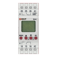
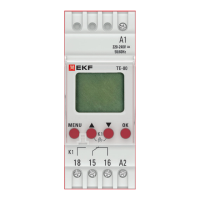
Connect power conductors to timer terminals L and N. The
normally open output contacts of the timer (terminals 18, 28 -
normally open; 16, 26 - normally closed; 15, 25 - common) are
connected in the break in the phase wire of the power supply of
the two load groups or in the break in the power supply wire of
the executive element of the switching device, such as the control
coil for contactor.
3.1 SETTINGS AND PROGRAMMING
Initial settings:
When the timer is turned on for the rst time (or
after a reset), you can use the buttons «▲▼»
and «OK» to set the language, date and time.