10
Code 3.4 and 3.2 Electromagnetic brake cable issue or electromagnetic brake failure
Use a multimeter to measure the resistance of the two-core plug-in on the controller.
Shown below
Code 4.1 Motor or motor wire shot circuit or controller failure.
Remove the motor brake disc (the brake cable is still connected), Connect the motor M1
and M2 to the positive and negative pole of the battery, and observe whether the motor
rotates normally. If not, there is a motor issue. If the motor rotates normally, the controller
should be issue.
Code 3.5 and 3.1 Operation sequence failure
1. Under normal conditions of the interlock switch, use a Multimeter to measure the
voltage between J1-6 and negative pole on the 14-core plug-in of the controller when bend
the handle to operating handle there is a voltage of about 24V.
2.If not, Check the interlock switch. For example, you can observe whether the switch light
is on or not whether the signal pass through wire to controller.
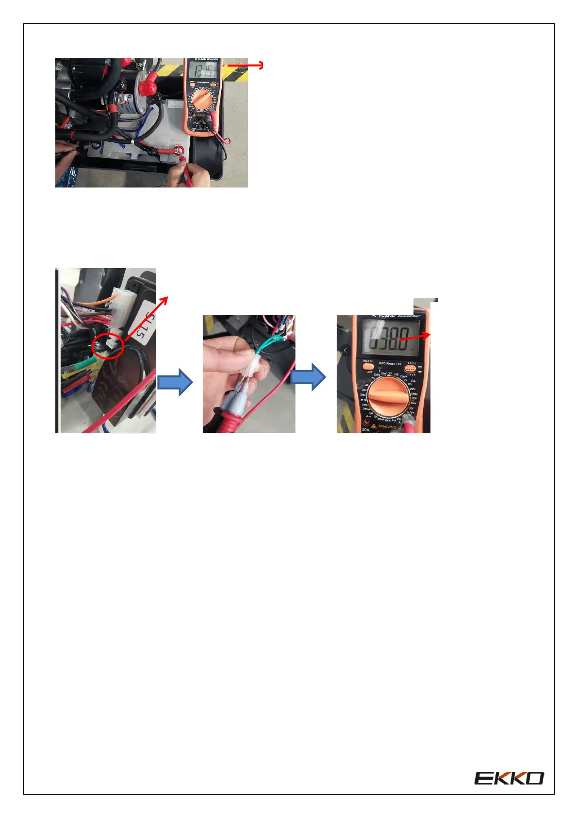
Code 4.2 Motor Voltage can’t match the accelerator input, The motor or motor ring short
circuit and controller failure. Troubleshooting operations as below steps.
Battery cell with load measurement, Cell voltage
drop should between 2-3V.
Unplug 2-core plug in of the controller. Turn the
multimeter to 200Ω, and measure the resistance
between the two wires on the plug-in