Do you have a question about the EKKO EB12E-119 and is the answer not in the manual?
Overview of hydraulic, mechanical, electrical, brake, and battery systems.
Details on where and how to lubricate machine components.
Guidelines for checking and refilling hydraulic oil based on temperature.
Information on identifying and checking electrical fuses.
Identifies common malfunctions, their causes, and solutions.
Explains controller fault codes and their meanings.
Step-by-step troubleshooting for typical operational issues.
Methods for quickly diagnosing controller failures.
Electrical schematic of the machine's control system.
Diagram illustrating the machine's hydraulic system.
Procedures and criteria for inspecting hydraulic oil quality.
Guide on adjusting the electromagnetic brake gap and function.
Steps for disassembling the drive assembly and its components.
Process for removing brake components and driving wheels.
Identification of internal gears and bearings within the drive system.
Overview of the operating handle assembly and its controls.
Details on the mechanical structure of the electric stacker.
Specifics on the fork carriage assembly for economic models.
Information about the pump motor and its associated valves.
Details the menu hierarchy and navigation of the programmer.
Guide for using the programmer to diagnose system faults.
Explains saving and restoring parameter files using the programmer.
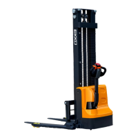
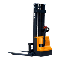
This document is a service manual for the EKKO Walkie Electric Stacker, covering models EB12E-119/138, EB12E-98Li, EB13E-119/138, EB13ES-145Li, and EB13E-119/138/145 Li. It provides essential information for understanding, operating, and maintaining the equipment, emphasizing the importance of reading and comprehending the instructions before use. A warning highlights the necessity of understanding the operation instructions to ensure safe usage. Users are also advised to check the last page of the document and the product type identification on the nameplate, and to keep the manual for future reference.
The manual begins with a comprehensive maintenance list, detailing various checks and tasks for the hydraulic, mechanical, electrical, and brake systems, as well as the battery and charger. This list is organized by time intervals (1, 3, 6, and 12 months), allowing for scheduled maintenance. For the hydraulic system, tasks include checking the hydraulic cylinder, piston, and connectors for damage, noise, and leakage, as well as monitoring and refilling hydraulic oil. The mechanical system requires inspecting the fork, chassis, push rod, gearbox, and wheel rod for deformation or damage, ensuring all screws are fastened, and lubricating steering bearings and pivot points. Electrical system maintenance involves checking power wiring, electrical connections, emergency switch function, drive system for noise, electricity meter, fuses, warming signals, contactor, and insulation of the frame, along with assessing the drive controller and motor. The brake system requires checking brake performance and adjusting the air gap if necessary. Battery maintenance focuses on checking voltage, terminals for corrosion and damage, and lubricating them, as well as inspecting the battery cover. Charger checks include the main cable and startup protection program during charging. Finally, functional checks cover the horn, solenoid valve air gap, emergency braking, reverse braking, regenerative braking, emergency reverse switch, steering, lifting and lowering, and handle proximity switch. Comprehensive checks ensure all labels are clear, bearing wheels are adjusted or replaced if worn, and a test run is performed.
Lubrication points are clearly identified, with instructions to use DIN51825 standard grease for marked points such as the tapered bearing and butter filler. The manual also specifies lubrication for the sliding way in the mast and the chains. For hydraulic oil, the manual provides a table with recommended oil types based on temperature ranges, along with viscosity and oil volume. It emphasizes that waste materials like oil and batteries must be processed and recycled according to national regulations. The oil level should always be above the minimum required for the truck to operate, and users are instructed to add oil to the filling points if needed. Electrical fuses are also detailed, with specifications for a 10A fuse and a 200A fuse, and visual aids to help locate them.
The failure analysis section is crucial for troubleshooting. It includes a table of common malfunctions, their causes, and corresponding solutions. For instance, if goods cannot be lifted, potential causes range from overload and battery discharge to a damaged lift fuse, low hydraulic oil, oil leakage, or high oiliness. Solutions include checking the nameplate for max capacity, charging the battery, replacing fuses, refilling hydraulic oil, checking seals, and reducing oiliness. If the truck cannot operate, causes might be a charging battery, disconnected battery, damaged fuse, low battery, activated emergency switch, or the handle not being in the operating area. Solutions involve ensuring the battery is fully charged and connected, replacing fuses, turning the emergency switch clockwise, or moving the handle to the operating area. The manual also provides guidance on what to do if the truck breaks down outside the working area, advising to jack it up, place a load handling device for safety, and move it to a tunnel.
A detailed section on controller fault code display lists various fault codes (e.g., BATTERY DISCONNECT FAULT, BRAKE OFF FAULT, HPD FAULT, OVERVOLTAGE FAULT) with their corresponding failure phenomena and troubleshooting steps. For example, a "Battery disconnected" fault (Code 4.5) could mean the battery is not connected or has a poor connection to terminals. Troubleshooting for common faults, such as Code 4.5, involves checking cable terminals for looseness and measuring battery cell voltage under load. For electromagnetic brake issues (Code 3.4 and 3.2), users are instructed to measure the resistance of the two-core plug-in on the controller. Motor or motor wire short circuit/controller failure (Code 4.1) involves removing the motor brake disc and connecting the motor directly to the battery to check rotation. Operation sequence failures (Code 3.5 and 3.1) require measuring voltage at the interlock switch and checking its functionality. The manual also provides steps for quick determination of controller failure, including checking accelerator voltage output, short-circuiting specific pins, and testing the brake and motor directly.
The manual further addresses issues with lifting and lowering, or if the oil cylinder lowers itself. Troubleshooting involves checking the coil wiring of the lifting contactor for voltage, observing the red light of the lower solenoid valve signal, and inspecting the solenoid valve core. If the truck cannot lift goods normally, the manual explains how to adjust the oil pump pressure to match the rated loading capacity, cautioning against exceeding the rated load to prevent frame deformation. This adjustment involves unscrewing a pressure screw cap and using an allen wrench.
Wiring and circuit diagrams are provided, including a detailed circuit diagram with a key for components like switches, contactors, accelerator, motor, and fuses. An oil hydraulic circuit diagram illustrates the lifting cylinder, lowering valve, pressure controller valve, hydraulic power unit, and oil tank. Hydraulic oil inspection guidelines are given, with a table describing different oil conditions (clear, transparent, milky, dark brown, clear with black spots), their smell, and the recommended action (e.g., check viscosity, separate water, replace oil, filter).
Disassembly instructions for main parts are included, starting with electromagnetic brake adjustment, which involves adjusting a nut to achieve a specific gap (25-35CM). The manual notes that the brake cannot be properly connected when energized in the free state and requires external force or installation. Disassembly of the driving assembly is broken down into steps, from unscrewing brake screws to removing the driving wheel and its components. Disassembly of the brake and driving wheel is also detailed, with specific instructions for removing cables, screws, and circlips. Driving internal gears and bearings disassembly covers removing the gearbox cover, screws, and then the gear ring, bearings, and circlip.
The operating handle assembly section provides an overview of its components, including the handlebar, emergency reversing button, low speed button, lift/lower buttons, FWD/BWD turning knob (accelerator), micro switch, and electricity meter. It explains the electricity meter's display of power levels (red, yellow, blue, green) and how it connects to the power supply. The functions of each pin on the accelerator are also described. The mechanical part of the electric stacker highlights the adjustment hole for roller adjustment, noting that two screws are used for adjustment and locking, and the locking screw must be loosened before adjusting. A limited micro switch is also pointed out.
The economic electric stacker fork carriage assembly section shows components like side pads and rollers, and reiterates the adjustment hole mechanism for roller adjustment. Finally, the pump motor section details each valve core of the pump station, including the drop solenoid valve, descending valve, and check valve pressure valve. It explains their functions, common issues like blockages or loose screws, and how to troubleshoot them. For instance, the descending solenoid valve has a manual pressure relief screw, and if loose, it should be tightened. The descending valve adjusts speed and prevents rapid falling, and blockages can cause slow or no drop. The pressure valve adjusts oil pressure, and the one-way valve ensures one-way oil circulation, with foreign matter potentially causing self-falling.
The manual concludes with information on the CURTIS handle programmer, outlining its operation precautions, main function (inspection and maintenance), and warning against adjusting controller parameters to avoid accidents. It explains that the programmer can be connected whether the controller is powered on or off. Instructions are provided for reading fault codes (connecting, finding "Faults" in the menu, running the unit) and for signal detection (connecting, finding "Monitor," opening sub-items, observing value changes). The programmer's manual content describes the Curtis 1313 handheld programmer's use for configuring the electronic control system, adjusting parameters, real-time monitoring, and fault diagnosis. A critical warning emphasizes that incorrect programming can lead to dangerous situations and should only be performed by the truck manufacturer or authorized service agent. The programmer has two interfaces (for electronic control and PC), a battery box, and a memory card slot. Powering on the programmer involves inserting its connecting wire into the controller's programming port, after which it automatically powers on and displays control information.
The programmer's menu structure is detailed, showing nine sub-menus with specific icons, arranged hierarchically. Users can navigate through folders to access information and execution commands. The fault diagnosis menu allows users to view "Present Errors" (current faults) and "Fault History" (historical faults). It explains how to confirm if a fault is temporary and how to clear historical faults. The programmer menu also enables saving and restoring parameter setting files (.cpf files), allowing users to back up current settings and restore previously saved configurations.
| Power Source | Electric |
|---|---|
| Fork Length (in) | 45.3 |
| Material | Steel |
| Operating Temperature | 14°F to 104°F |
| Load Capacity | 119 lbs |