© ELAN 2015 All rights reserved. Page 11
ELAN
gMV88 INSTALLATION MANUAL
6 7 8
6 7 8
17 18 19 25 26 27 28 29
31 32
ARP41
ARP42
ARP43
ARP44
ARP45
ARP46
ARP47
ARP48
ETHERNET
RS-232
HDMI
HDBASET
IR
IN
IR
OUT
1 2 3 4 5 6 7 8
VIDEO OUTPUTS
FIGURE 1-X13
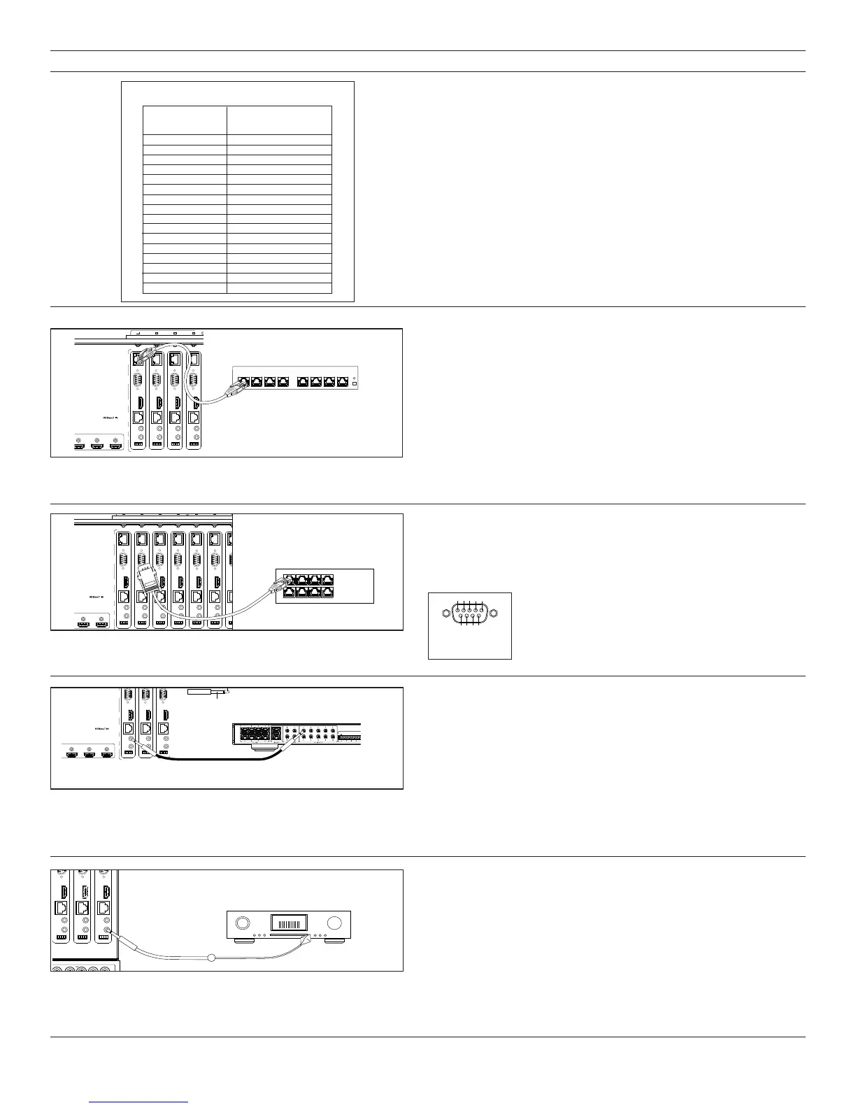
ETHERNET SWITCH
Figure 1 X14 Connecting Serial to the HDBaseT output (Zone 2
showed for example)
HDBaseT Disribution Connections
Ethernet (18) – Each zone output has a connection for 10/100 Ethernet.
Connection to an Ethernet switch should be done with appropriately rated
cable and need only be made if you are going to utilize Ethernet at the
destination room for a Smart TV, game station, media player or the like.
Ethernet signal distribution over HDBaseT requires use of the ELAN HDRE
as the HDBaseT receiver.
Figure 1 X13 Connecting an Ethernet jumper to the HDBaseT
(Zone 2 showed for example)
Serial (17) – Industry standard DB9 connectors are used to connect g!
serial control signals to equipment at the destination room at baud rates
upto115K.UseELANpartno.8900597toconnectaCAT-5cabledirectly
from the g! controller output to the zone specific serial connector.
7 8
7 8
17 18 19 25 26 27 28 29
31 32
21 22 23 24
ARP41
ARP42
ARP43
ARP44
ARP45
ARP46
ARP47
ARP48
ETHERNET
RS-232
HDMI
HDBASET
IR
IN
IR
OUT
1 2 3 4 5 6 7 8
VIDEO OUTPUTS
FIGURE 1-X14
gSC10
1 2 3 4
5 6 7 8
8900597
Serial RS-232 connector pin-out
5 4 3 2 1
Pin definitions
1 - No Connect
2 - TX
3 - RX
4 - No Connect
6 - No Connect
7 - No Connect
8 - No Connect
9 - No Connect
9 8 7 6
IR In (14) – IR inputs are zone specific and are generally connected to g!
controller IR outputs with a 1/8” (3.5mm) mono mini to 1/8” mono mini
cable. Use this connection to operate monitors and sources in the destina-
tion room. g! controllers allow many sources to be connected to the same
IR output, so as long as you do not have duplicate devices in the destina-
tion room you will have no problem operating several IR devices with one
connection using an IR connecting block like the Xantech 789-44 on the IR
output of the HDRE or HDRS.
IR output (15) – zone specific outputs provide access to IR signals
generated in the destination room. Unless you have connected an IR
receiver to the HDRE HDBaseT receiver to control a centrally located
g1 OSD interface it is unlikely you will utilize these connections. If you have
an IR controlled device not related to the A/V system it is possible that this
connection could be used for that.
Figure 1 X15 Connecting IR to the HDBaseT output (Zone 2
showed for example)
MAIN POWER
28 29 31 32
36 37 38 39
21 22 23 24
28 29 31 32
ARP46
ARP47
ARP48
AV / SOURCE
FIGURE 1-X16
† Digital zone outputs configured to access analog inputs create a
mirrored digital and analog output situation. The g! configuration software
will manage the situation and you can refer to this chart to make sure that
you do not mis-connect an output.
When Digital outputs are configured to mirror Analog outputs the output
level becomes variable and matches the output level of the analog outputs.
When analog inputs are routed to digital outputs the digital output
and an analog output mirror each other
Digital Mirrors Analog
Output # Output #
1
2
3
4
5
6
7
8
9
10
11
12
13
14
15
16
17
18
19
20
21
22
23
24
25
26
27
28
29
30
31
32
Figure 1 X16 Connecting HDRE to gMV with HDBST, and IR Out on
GMV connected to g1 Input.
MAIN POWER
6 7 8
6
14
6
14
7
15
7
15
8
16
8
16
17 18 19 25 26 27 28 29
31 32
21 22 23 24
33 34 35 36 37 38 39
17 18 19 21 22 23 24
25 26 27 28 29
31 32
ARP41
ARP42
ARP43
ARP44
ARP45
ARP46
ARP47
ARP48
ETHERNET
RS-232
HDMI
HDBASET
IR
IN
IR
OUT
1 2 3 4 5 6 7 8
VIDEO OUTPUTS
This device compli es with part 15 of the FCC Rules.
Operation is subject to the fol lowing two conditions :
(1) this device may not cause harmful interfer ence and
©2015 Core Brands, LLC , Petaluma CA. Made in the USA.
FIGURE 1-X15
gSC10
TIP - SIGNAL
RING - GROUND
 Loading...