09/2013 - Art. Nr. 4200 1053 2900A8
Operation
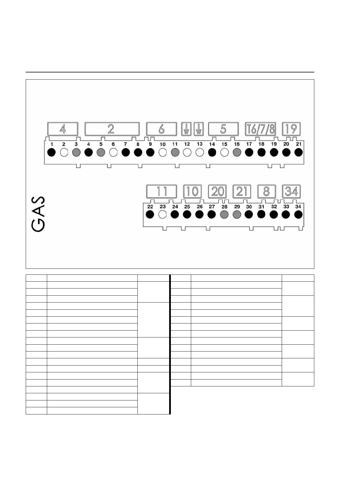
Terminal allocation chart
230 Volt connection
Earth
Flame check
Fault
display
Air pressure
switch
Igniter
Burner motor
Connector
Terminal
Terminal
Connector
Remote
unlocking
L1 power
supply
Solenoid valve
Control
thermostat
Heating
request
Earth
Gas pressure
switch
Terminal Description Connector Terminal Description Connector
1 Burner motor live
4
20 Minimum output thermostat live (T1)
19
2 Earth 21 Heating request signal (option T2)
3 Neutral 22 Flame monitoring signal
114 Solenoid valve live
2
23 Earth
5 Neutral 24 Live
6 Earth 25 Air pressure switch signal
10
7 Solenoid valve live 26 Live
8 Live 27 Live
20
9 Live L1
6
28 Remote unlocking signal
10 Earth 29 Neutral
21
11 Neutral 30 Signal fault live
12 Earth 31 Live
8
13 Earth 32 Live
14 Igniter live
5
33 Not used
34
15 Earth 34 Not used
16 Neutral
17 Control thermostat live
T6/7/8
18 Signal T7
19 Signal T8
 Loading...