NOTE: The symbol following the Cos value = capacitive load.
Instrument set-up
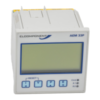
To enter programming mode press and simultaneously for 5 seconds. The display shows the
CT settings screen. The instrument settings are entered from this point, starting with the CT values.
CT SET-UP
The CT primary value may then be set from the following nominal values (secondary value must be
5A):
5, 10, 15, 20, 30, 40, 50, 60, 80, 100, 150, 200, 250, 300, 400, 500, 600, 800, 1000, 1200, 1250, 1500,
1600, 2000, 2400, 3000, 2500, 4000, 4500, 5000, 5500, 6000, 6500, 7000, 7500, 8000, 8500, 9000,
9500, 10000, 10500, 11000, 11500, 12000, 12500, 13000, 13500, 14000, 14500, 15000, 15500,
16000, 16500, 17000, 17500, 18000, 18500, 19000, 19500, 2000, 205000, 21000, 21500, 22500,
23000, 23500, 24000, 24500, 25000
Press the or key until the desired current is displayed. If the desired CT value is not present in
the above list, the ratio may be ‘fine adjusted’ as follows: Press and hold the and buttons
simultaneously for 2 seconds to enter ‘Fine Adjust Mode’. This is indicated by the ‘L’ symbol at the
bottom left of the display changing to ‘F’ (Fine). Find mode allows the CT primary value to be
changed in steps of 10A until the desired ratio is displayed.
Press the key to store the value and advance the page.
System Average Demand
Rolling average of user
defined MD period
System Max Demand
Maximum recorded
average demand value