5
1.3 Technical Specications
Electrical and mechanical specications
Supply voltage
10-24V50Hz~200mAmax/10-24V 200mAmax
Current used in standby mode 50mAmax
GSM modem frequency 850/900/1800/1900 MHz
Numberof“low”level(negative)inputs 4
Numberof“high”level(positive)inputs 1
Allowable„low“level(negative)inputvalues Voltage: 0... 1.6V; current: -0.8... -0.4mA
Allowable„high“level(positive)inputvalues Voltage: 5... 50V; current: 0.17.... 1.7mA
Number of outputs 1
Output type NO(relay)
Relayoutputmaximumcommutatingvalues 24V 1A / 24V 50Hz ~0,5A
Dimensions 82x63x20mm
Operating temperature range -20…+55
o
C
(-30...+55
o
Cwithlimitations)
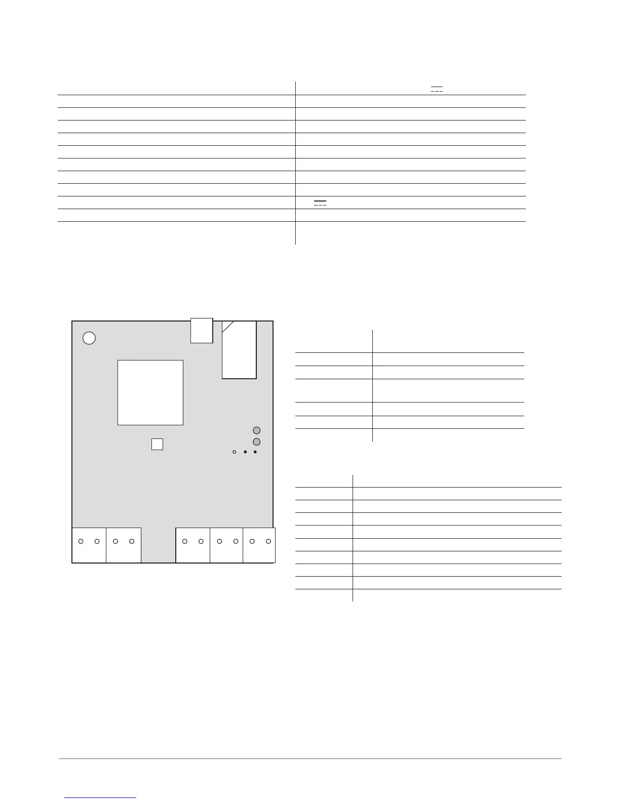
1.4 Connector Functionality
ANT
GSM
MODEM
SIM
CARD
MIC
LED1
LED2
DEFAULT
D1 D2
AC/DC
RELAY
COM- -
Z5
Z4 Z3
Z2 Z1
USB
Short explanation of the main units
GSM MODEM GSM network 850/900/1800/1900 MHz
modem
SIM CARD
SIM card
LED
Light-emitting diodes indicator
DEFAULT
Connectors(D1andD2)forrestoring
default settings
ANT
GSM antenna SMA type connector
USB Mini USB connector
F1
Fuse
Connector functionality
Labeling Explanation
AC/DC Power supply pins
RELAY Dryrelaycontact.Normallyopen(NO)
RELAY Dryrelaycontact.Normallyopen(NO)
COM Common pin
Z5 “Low” level input Z5
Z4 “Low“ level input Z4
Z3 “Low” level input Z3
Z2 “High” level input Z2
Z1 “Low” level input Z1
Picture 1