Page 1Rev 4-7-2022 The content of this document is subject to change without notice.
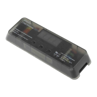
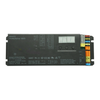
Wiring Diagram LINEARdrive 720D (LIN720D3)
2
1
0.2-1.5 mm
2
2
1
9 mm
0.35 inch
0.5-1.5 mm
2
AWG 20-16
9 mm
0.35 inch
AWG 24-16
LINEARdrive 720D
Other connectors:VDC and LED connectors:
LED Group 1
Group 1 GND
LED Group 2
Group 2 GND
LED Group 3
Group 3 GND
LED Group 4
Group 4 GND
V+
R
G
B
W
Pos (+)
Line
Neutral
Neg (-)
Ext in -
Ext in +
DA +
DA -
DA +
DA -
DMX in +
DMX in -
DMX in shield
VDC IN +
12-48 VDC Supply Voltage for Driver
(can be connected to PSU)
External control device
DALI network
DMX
VDC IN -
Terminal Block
RGBW LED Strip
PSU
CAUTION: The device may only be connected and installed by a qualied electrician. All applicable regulations, legislation and build-ing
codes must be observed. Incorrect installation of the device can cause irreparable damage to the device and the connected LEDs.
12V - 48V DC In
These connectors supply power to the LINEARdrive control
and processing circuitry and must be connected. To connect
to a 12-48V DC power supply unit (PSU), connect the PSU’s
positive voltage supply wire to the VDC+ connector and the
PSU’s negative voltage supply wire to the VDC-connector. The
driver and LEDs can use the same PSU.
Ext In
You have the possibility to connect an external control device
(10kΩ potentiometer or show selection switch) to the driver’s
Ext in+ and Ext in- connector. Congure the driver for use with
an external control device over the 3-button user interface.
DA+ / DA-
Use these connectors to connect the driver to a DALI network.
Always combine a DA+ and a DA- connector for either data
in-put or data output.
DMX In / Out
Use these connectors when the driver is used in a DMX network.
For DMX in/out, connect the network cable’s DMX+, DMX- and
DMX shielding wire (the orange/white, orange and brown wire
in a CAT5 cable) to the DMX in+, DMX in- and DMX in shield
connector respectively.
LED Groups
Indicates the location of the connectors for your LED groups.
R(ed) represents channel 1, G(reen) represents channel 2,
B(lue) represents channel 3 and W(hite) represents channel
4. The default group color allocation can be changed over the
3-button user interface.