© 2013 eldoLED. All rights reserved. V2.4
More product documentation and eldoLED’s terms and conditions are available at www.eldoled.com.
Pay attention when connecting the LED groups:
• polarity reversal results in no light output and often damages the LEDs
• combining + and - of different groups damages the driver
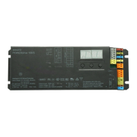
Wiring diagram POWERdrive 106/S (PWR106S1)
WARNING: Risk of electrical shock. May result in serious injury or death. Disconnect power before servicing or installing.
CAUTION: The device may only be connected and installed by a qualified electrician. All applicable regulations, legislation and build-
ing codes must be observed. Incorrect installation of the device can cause irreparable damage to the device and the connected LEDs.
120-277VAC
The driver accepts a universal mains voltage input of 120-277VAC,
50/60Hz.
DALI
Use these connectors to connect the driver to a DALI network. Always
combine a DA+ and DA- connector for either data input or data output.
DMX in/LedSync out
Use these connectors when the driver is used in a DMX network. For
DMX in, connect the network cable’s DMX+, DMX- and DMX shielding
wire (the orange/white, orange and brown wire in a CAT5 cable) to the
DMX in+, DMX in- and DMX in shield connector respectively. For
LedSync out, connect the network cable’s DMX+, DMX- and DMX
shielding wire to the LedSync out+, LedSync out- and LedSync shield
connector respectively.
LED wire length
Maximum wire length from LED driver to LED engine at full load:
Ext in
You have the possibility to connect an external control device (0-10V
control device, 10kΩ potentiometer or show selection switch) to the
driver’s Ext in+ and Ext in- connectors. Configure the driver for use
with an external control device over the 3-button user interface.
LED groups
Indicates the location of the connectors for your LED groups. R(ed)
represents channel 1, G(reen) represents channel 2, B(lue) repre-
sents channel 3 and W(hite) represents channel 4. The default group
color allocation can be changed over the 3-button user interface.
Output voltage vs output current for 4 outputs with symmetrical load
Vf
typ
is 57V, LED current ranges from 200mA - 1050mA
LEDcode/NTC
Use these connectors to connect a 47kΩ NTC thermistor for closed
loop LED engine temperature control.
AWG value 20 19 18 17 16
Distance (m)1418222836
Distance (ft) 45.9 59 72.2 91.9 118.1
Please observe voltage drop over long wire lengths.
Longer wire lengths increase EMI susceptibility.
0
1050
420
200
830
0
60V
30V
mA
Vf
4 LED groups,
4 control channels
LEDcode / NTC
+
-
+
-
+
-
DALI
{
N
L
VAC
120-277
DMX in shield
DMX in
-
DMX in +
LedSync out shield
LedSync out
-
LedSync out +
Ext in
-
Ext in +
2
1
9 mm
0.35 inch
0.5-1.5 mm
2
AWG 20-16